

| PROGRAMMING SCHOOL | Programming micro:bit in Python (Mu) |
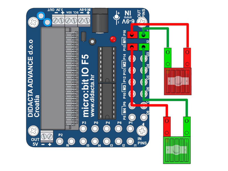
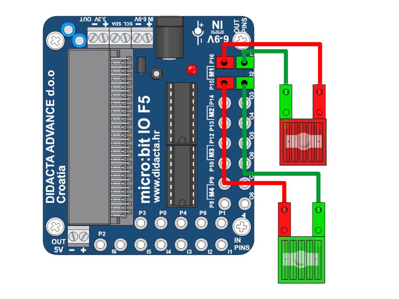
| 1. | STEP MOTOR | 8. | LIGHT CONTROLL - POTO sensor (DIGITALLY) B | ||||||
| 2. | ENCODER MOTOR - COUNTER CONTROL | 9. | LIGHT CONTROLL - POTO sensor (DIGITALLY) 2 | ||||||
| 3. | Controling LEDs with Potentiometer | 10. | LIGHT CONTROLL - POTO sensor (DIGITALLY) | ||||||
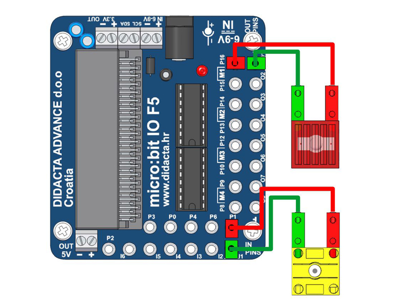
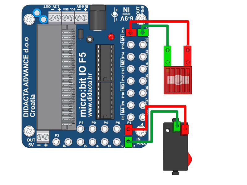
| 4. | MOTOR - ROTATION CONTROL WITH BUTTONS "A" AND "B" | 11. | LIGHT CONTROLL - PUSH BUTTON (DIGITALNO) | ||||||
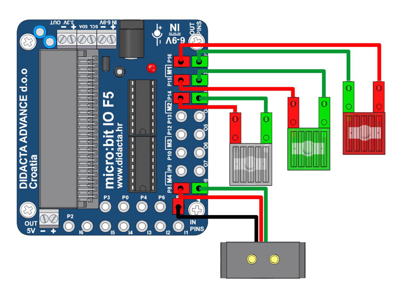
| 5. | COLOR SENZOR (FischerTechnik) - COLOR recognition | 12. | TWO LIGHTS CONTROLL WITH BUTTONS A AND B | ||||||
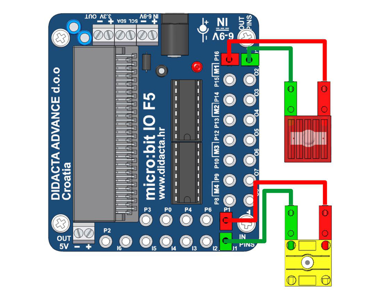
| 6. | LIGHT CONTROLL - POTO sensor (ANALOGUE) - RECOGNIZING BLACK LINE | 13. | TWO LIGHTS CONTROLL | ||||||
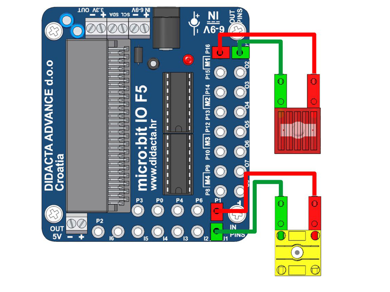
| 7. | LIGHT CONNTROL - POTO sensor (ANALOGUE) | 14. | LIGHT / LED CONTROLL | ||||||
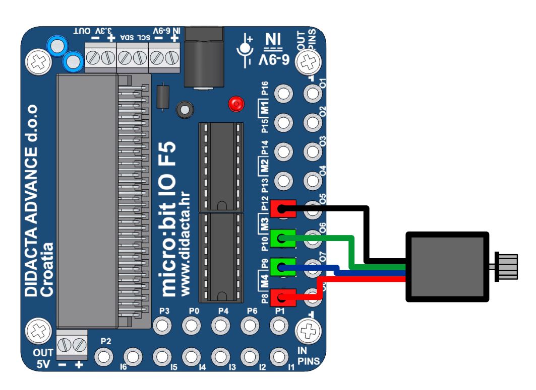
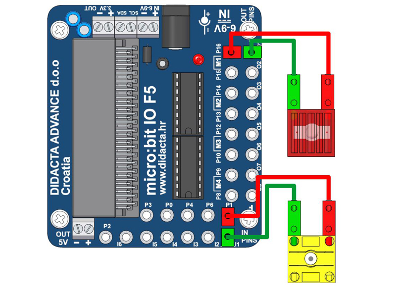
| STEP MOTOR | |||||||||||||||||||||||||||||||||||||||||||||||||||||||||||||||||||||||||||||||||||||||||||||||||||||||||||||||||||||||||||||||||||||||||||||||||||||||||||||||||||||||||||||||||||||||||||||||||||||||||||||||||||||||||||||||||||||||||||||||||||||||||||||||||||||||||||||||||||||||||||||||||||||||||||||||||||||||||||||||||||||||||||||||||||||||||||||||||||||||||||||||||||||||||||||||||||||||||||||||||||||||||||||||||||||||||||||||||||||||||||||||||||||||||||||||||||||||||||||||||||||||||||||||||||||||||||||||||||||||||||||||||||||||||||||||||
 | ||||||
| vjezba20.zip | ||||||
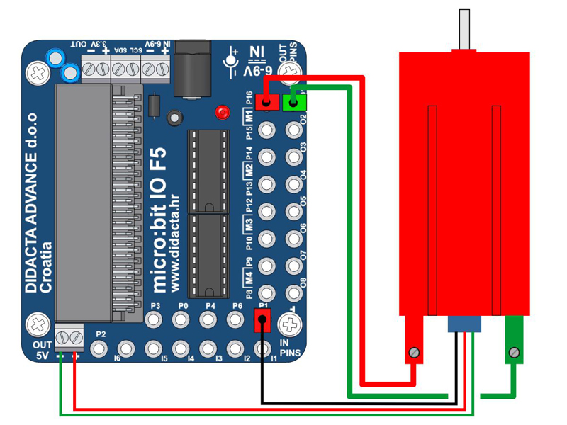
| ENCODER MOTOR - COUNTER CONTROL | |||||||||||||||||||||||||||||||||||||||||||||||||||||||||||||||||||||||||||||||||||||||||||||||||||||||||||||||||||||||||||||||||||||||||||||||||||||||||||||||||||||||||||||||||||||||||||||||||||||||||||||||||||||||||||||||||||||||||||||||||||||||||||||||||||||||||||||||||||||||||||||||||||||||||||||||||||||||||||||||||||||||||||||||||||||||||||||||||||||||||||||||||||||||||||||||||||||||||||||||||||||||||||||||||||||||||||||||||||||||||||||||||||||||||||||||||||||||||||||||||||||||||||||||||||||||
 | ||||||
| vjezba19.zip | ||||||
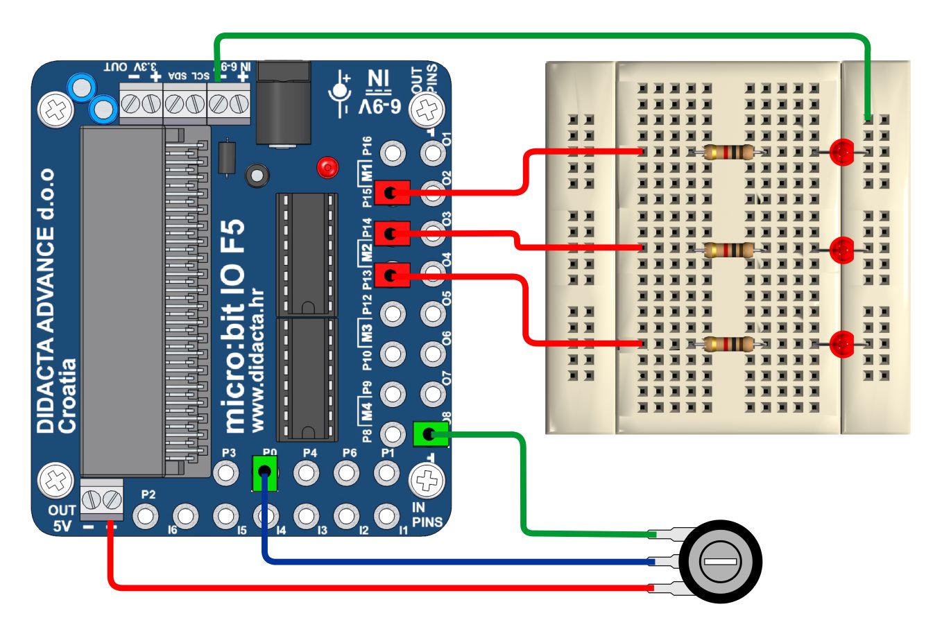
| Controling LEDs with Potentiometer | |||||||||||||||||||||||||||||||||||||||||||||||||||||||||||||||||||||||||||||||||||||||||||||||||||||||||||||||||||||||||||||||||||||||||||||||||||||||||||||||||||||||||||||||||||||||||||||||||||||||||||||||||||||||||||||||||||||||||||||||||||||||||||||||||||||||||||||||||||||||||||||||||||||||||||||||||||||||||||||||||||||||||||||||||||||||||||||||||||||||||||||||||||||||||||||||||||||||||||||||||||||||||||||||||||||||||||||||||||||||||||||||||||||||||||||
 | ||||||
| vjezba13.zip | ||||||
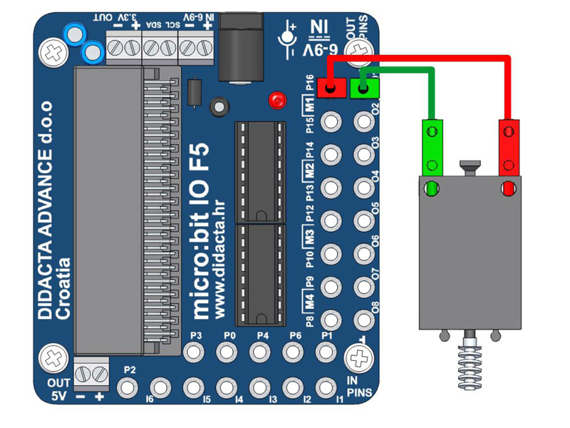
| MOTOR - ROTATION CONTROL WITH BUTTONS "A" AND "B" | |||||||||||||||||||||||||||||||||||||||||||||||||||||||||||||||||||||||||||||||||||||||||||||||||||||||||||||||||||||||||||||||||||||||||||||||||||||||||||||||||||||||||||||||||||||||||||||||||||||||||||||||||||||||||||||||||||||||||||||||||||||||||||||||||||||||||||||||||||||||||||||||||||||||||||||||||||||||||||||||||||||||||||||||||||||||||||||||||||||||||||||||||||||||||||||||||||||||||||||||||||||||||||||||||||
 | ||||||
| vjezba11.zip | ||||||
| COLOR SENZOR (FischerTechnik) - COLOR recognition | |||||||||||||||||||||||||||||||||||||||||||||||||||||||||||||||||||||||||||||||||||||||||||||||||||||||||||||||||||||||||||||||||||||||||||||||||||||||||||||||||||||||||||||||||||||||||||||||||||||||||||||||||||||||||||||||||||||||||||||||||||||||||||||||||||||||||||||||||||||||||||||||||||||||||||||||||||||||||||||||||||||||||||||||||||||||||||||||||||||||||||||||||||||||||
 | ||||||
| vjezba10.zip | ||||||
| LIGHT CONTROLL - POTO sensor (ANALOGUE) - RECOGNIZING BLACK LINE | |||||||||||||||||||||||||||||||||||||||||||||||||||||||||||||||||||||||||||||||||||||||||||||||||||||||||||||||||||||||||||||||||||||||||||||||||||||||||||||||||||||||||||||||||||||||||||||||||||||||||||||||||||||||||||||||||||||||||||||||||||||||||||||||||||||||||||||||||||||||||||||||||||||||||||||||||||||||||||||||||||||||||||||||
 | ||||||
| vjezba09.zip | ||||||
| LIGHT CONNTROL - POTO sensor (ANALOGUE) | |||||||||||||||||||||||||||||||||||||||||||||||||||||||||||||||||||||||||||||||||||||||||||||||||||||||||||||||||||||||||||||||||||||||||||||||||||||||||||||||||||||||||||||||||||||||||||||||||||||||||||||||||||||||||||||||||||||||||||||||||||||||||||||||||||||||||||||||||||||||||||||||||||||
 | ||||||
| vjezba08.zip | ||||||
| LIGHT CONTROLL - POTO sensor (DIGITALLY) B | |||||||||||||||||||||||||||||||||||||||||||||||||||||||||||||||||||||||||||||||||||||||||||||||||||||||||||||||||||||||||||||||||||||||||||||||||||||||||||||||||||||||||||||||||||||||||||||||||||||||||||||||||||||||||||||||||||||||||||||||||||||||||||
 | ||||||
| vjezba07.zip | ||||||
| LIGHT CONTROLL - POTO sensor (DIGITALLY) 2 | |||||||||||||||||||||||||||||||||||||||||||||||||||||||||||||||||||||||||||||||||||||||||||||||||||||||||||||||||||||||||||||||||||||||||||||||||||||||||||||||||||||||||||||||||||||||||||||||||||||||||||||||||
 | ||||||
| vjezba06.zip | ||||||
| LIGHT CONTROLL - POTO sensor (DIGITALLY) | |||||||||||||||||||||||||||||||||||||||||||||||||||||||||||||||||||||||||||||||||||||||||||||||||||||||||||||||||||||||||||||||||||||||||||||||||||||||||||||||||||||||
 | ||||||
| vjezba05.zip | ||||||
| LIGHT CONTROLL - PUSH BUTTON (DIGITALNO) | |||||||||||||||||||||||||||||||||||||||||||||||||||||||||||||||||||||||||||||||||||||||||||||||||||||||||||||||||||||||||||||
 | ||||||
| vjezba04.zip | ||||||
| TWO LIGHTS CONTROLL WITH BUTTONS A AND B | |||||||||||||||||||||||||||||||||||||||||||||||||||||||||||||||||||||||||||||||||||
 | ||||||
| vjezba03.zip | ||||||
| TWO LIGHTS CONTROLL | |||||||||||||||||||||||||||||||||||||||||
 | ||||||
| vjezba02.zip | ||||||
| LIGHT / LED CONTROLL | ||||||
 | ||||||
| vjezba01.zip | ||||||