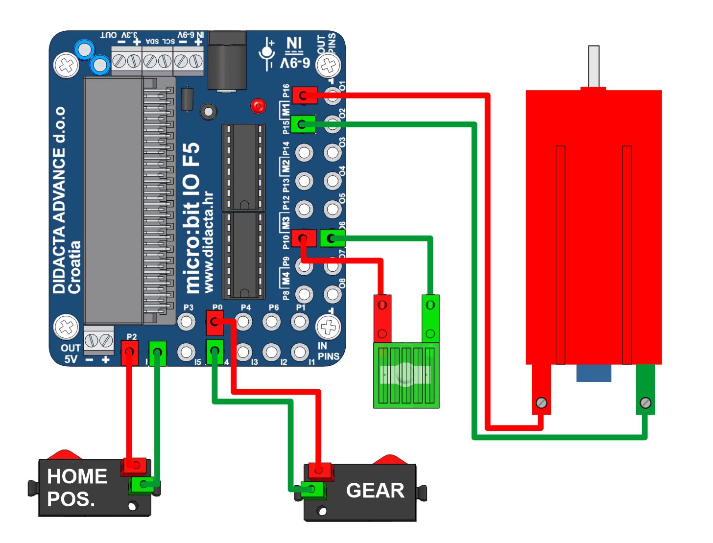
For precise positioning of the circular plate or the support of the robotic arm in this example, we used a stepping (pulse) gear. At the beginning, it is always necessary to set the board (arm support) to the initial position (home). After that, we can start the positioning program to a certain position. The example positions the circular panel to positions that are defined at an angle of 60 degrees, from the initial position ( home ). Using the "A" button, positioning is performed to the right (from the HOME position) by 60 degrees from the current position. Using the "B" button, positioning is performed to the left (toward the HOME position) by 60 degrees from the current position, and up to the HOME position at the maximum. Using the "A+B" button, the arm panel is positioned at the HOME position. Due to the difference in the operation of the engine and the friction that occurs in the transmission, the programs for right and left positioning are slightly different.
"Counter" and "pause" are used for adjustment. The counter counts both (0, 1) button positions of the step (pulse) gear.
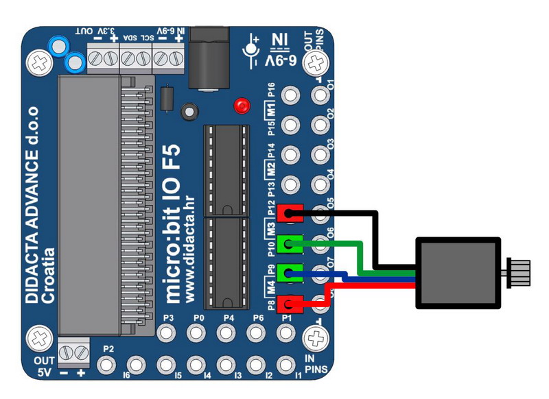
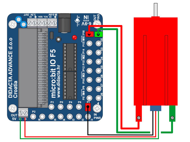
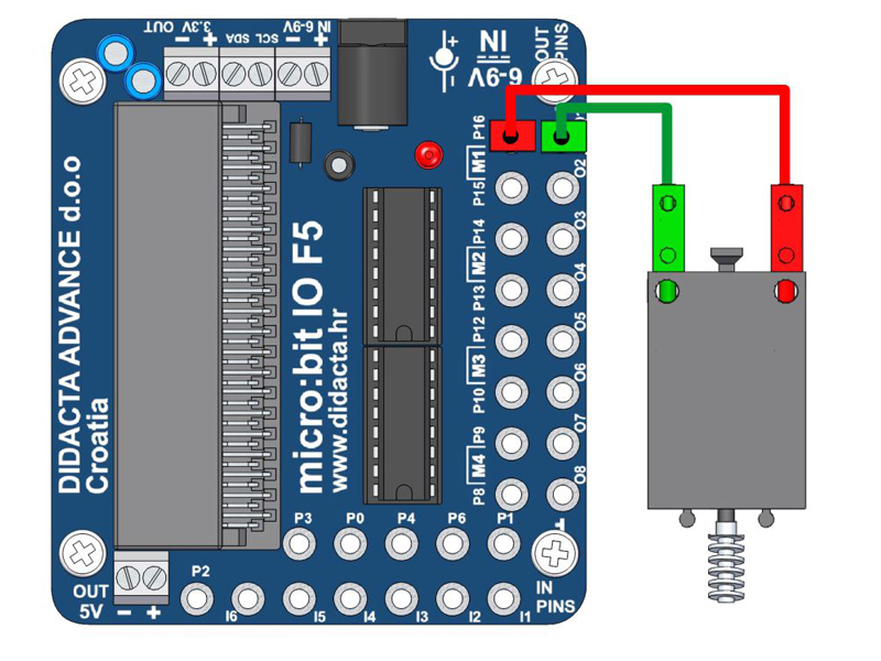
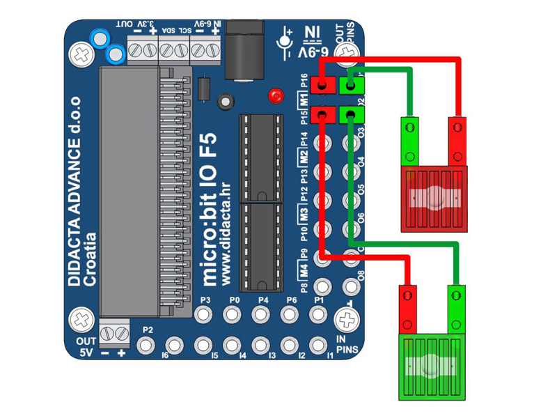
The micro: bit can control the operation of the stepper motor. This example shows the control of a stepper motor in one direction by a shift of HALF STEPS. To work in the opposite direction, the order should be reversed. By changing the value of the SPEED variable, we change the engine speed - turning the engine by one step. The motor in the example has a peak consumption of 600 mA, so the driver chips heat up a lot during longer operation. For longer operation, it would be necessary to select motors that have lower consumption or replace the L293D drivers with a version of the L293B that supports consumption up to 1000 mA per output. We use a 5V adapter for power supply.
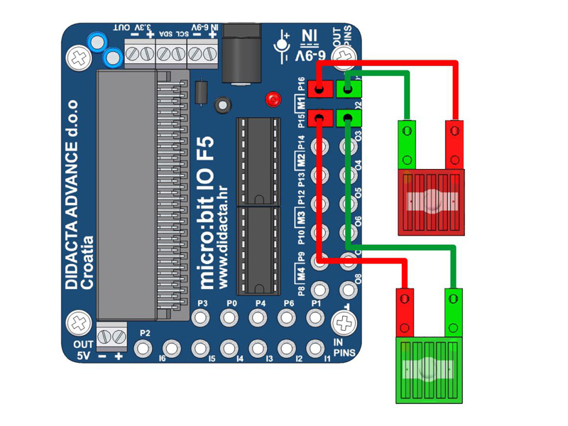
The micro: bit can control the operation of the stepper motor. This example shows a stepper motor control in one direction by a STEP offset. To work in the opposite direction, the order should be reversed. By changing the value of the SPEED variable, we change the engine speed - turning the engine by one step. The motor in the example has a peak consumption of 600 mA, so the driver chips heat up a lot during longer operation. For longer operation, it would be necessary to select motors that have lower consumption or replace the L293D drivers with a version of the L293B that supports consumption up to 1000 mA per output. We use a 5V adapter for power supply.
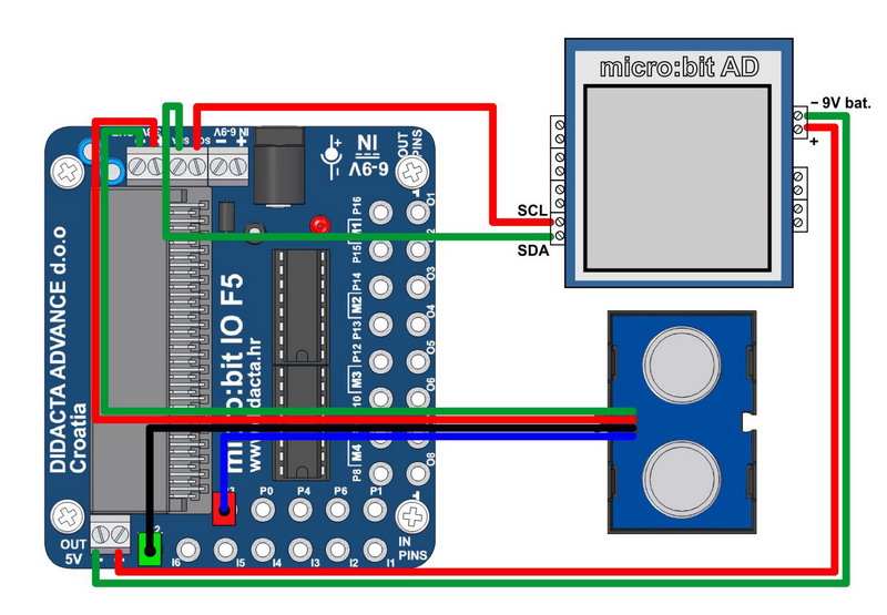
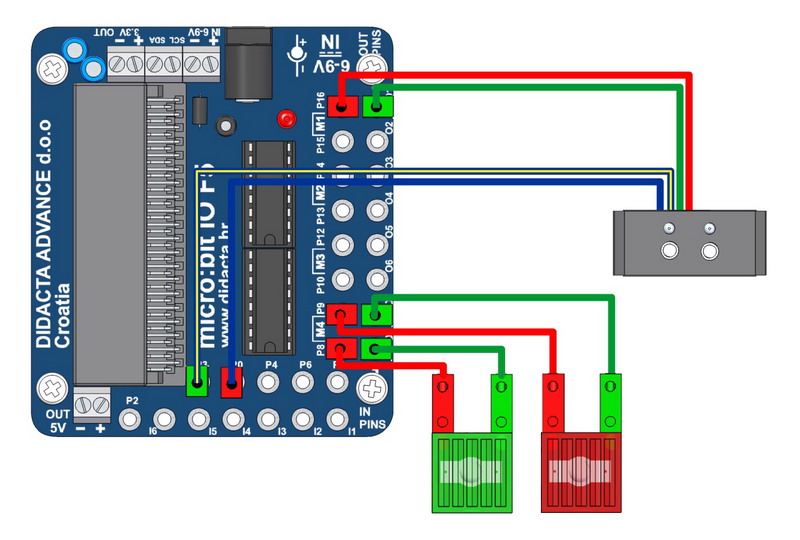
We can use the micro:bit AD interface to display the values when creating the program. We connect the interface via I2C communication and we can use all the functions built into the micro:bit AD interface. We can display data in text or graphic form. In this example, we use an ultrasonic sensor.
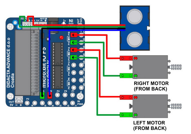
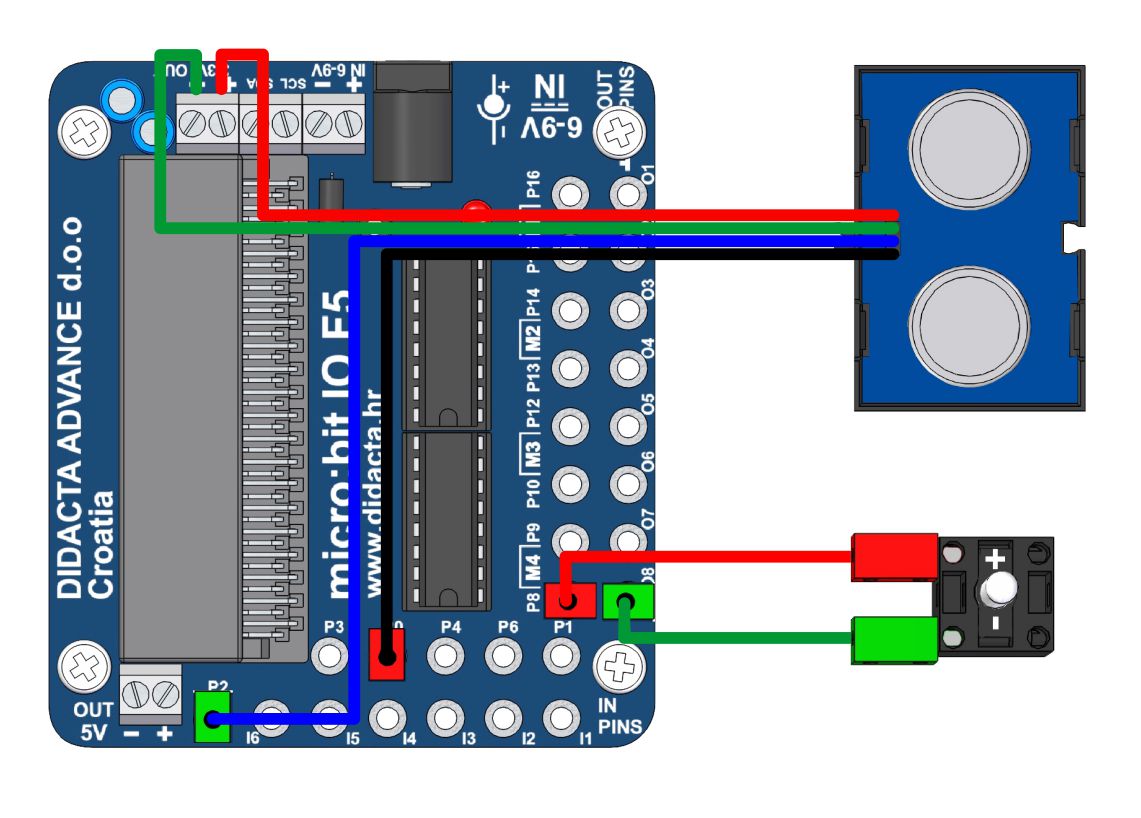
ULTRASOUND SENSOR (3.3V) - random car control ( change )
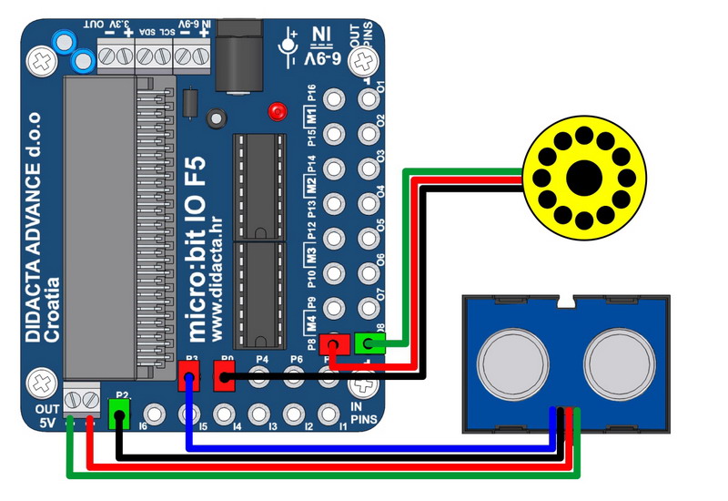
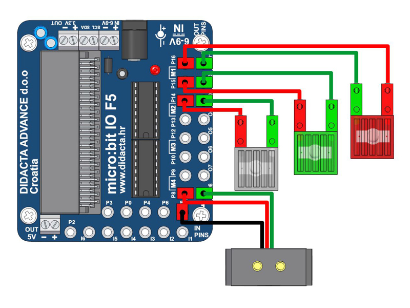
Connect the ULTRASONIC sensor to the 3.3V supply (red and green). Connect the signal wires to the input P0 (blue) and P3 (black).
Connect the right motor to the motor outputs M1 (P15 and P16), and the left at the motor outputs M2 (P13 and P14). ADD package "SONAR". The vehicle constantly moves forward (for a test if the engines are well connected). When the ultrasonic sensor detects an obstacle, the vehicle moves backwards and turns to the left or right according to random selection.
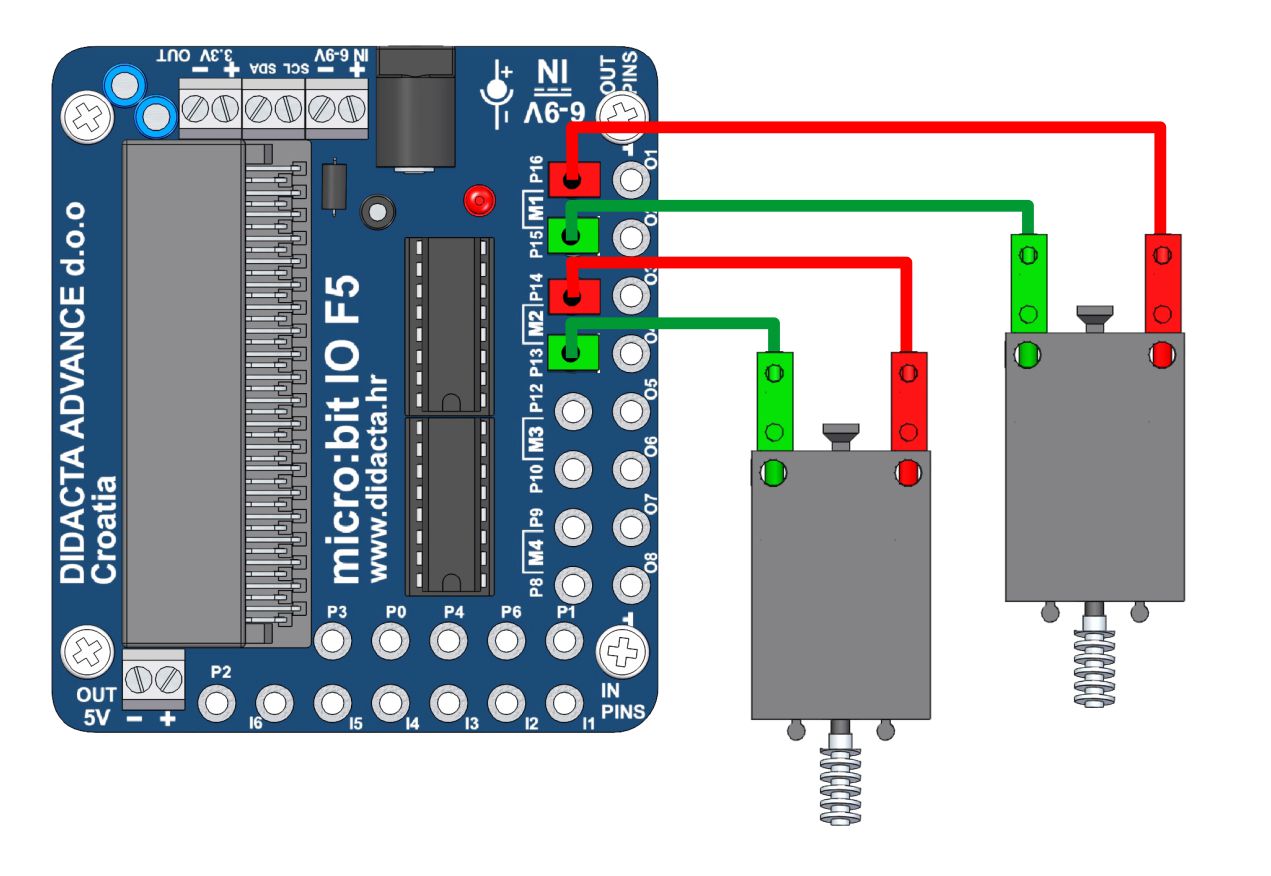
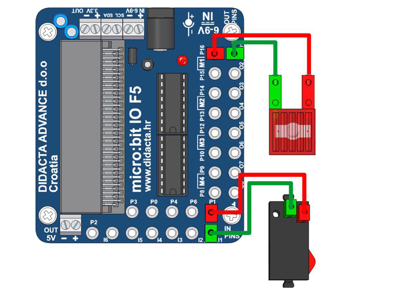
We can use it to detect a black line in a vehicle model that follows a black line, or we can use it as a white obstacle sensor (distance sensor). The Fischertechnik IR sensor consists of two sensors (blue wires) that detect a white (bright) surface.
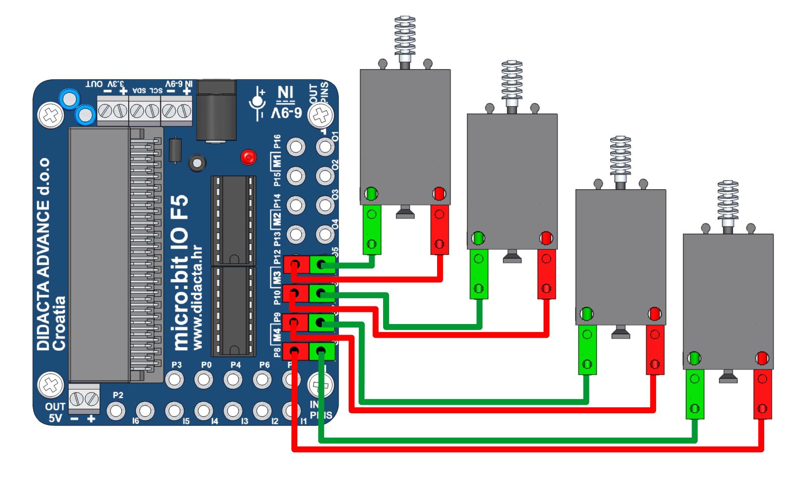
Speed control of four DC motors. Simulation of analog control via the "write digital" command. MakeCode has a limit of max. three outputs that can control analog. This is a method that works similar to the PWM control (write analog).
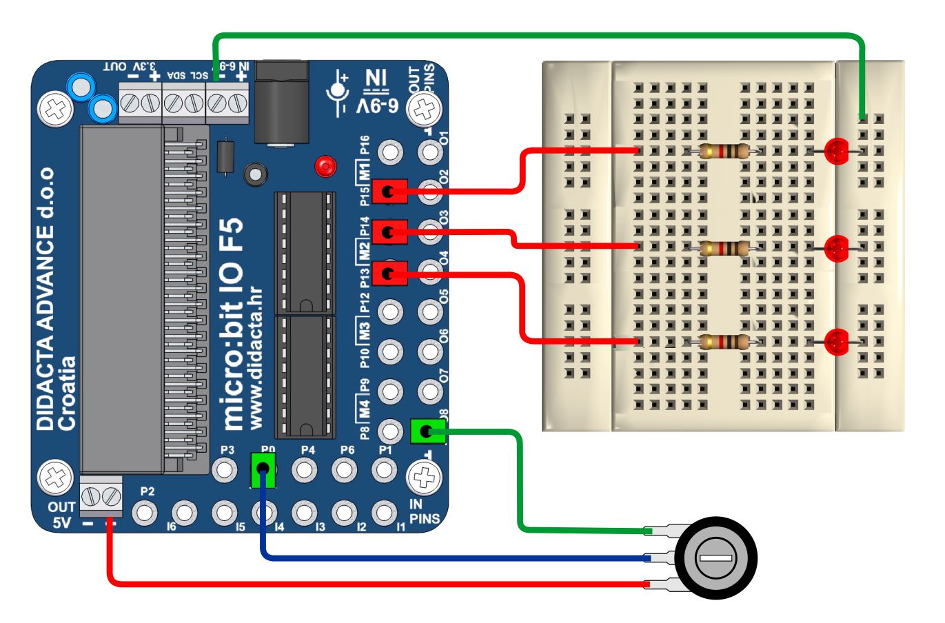
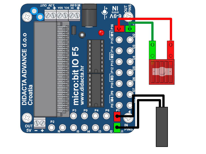
Turning the potentiometer turns on the LEDs. The potentiometer is connected to INPUT P0 and reads analogously. The interface is powered by a universal 5V adapter.
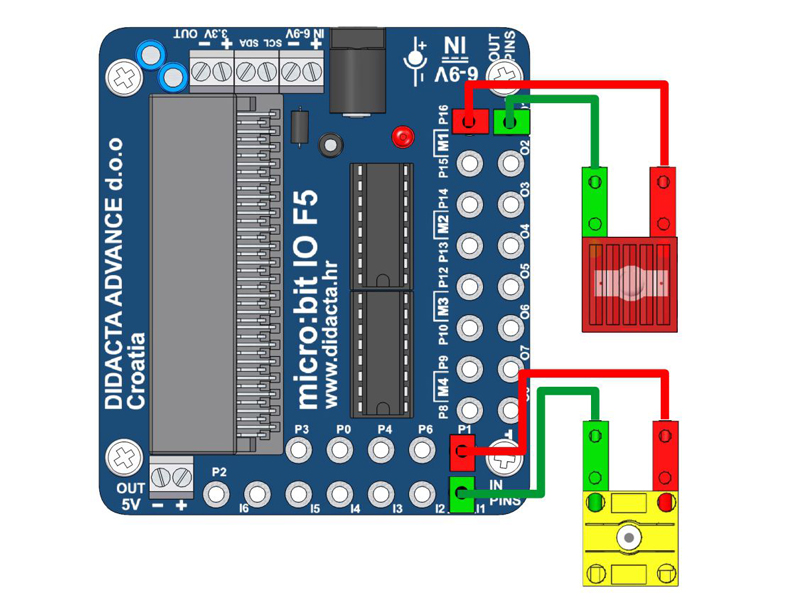
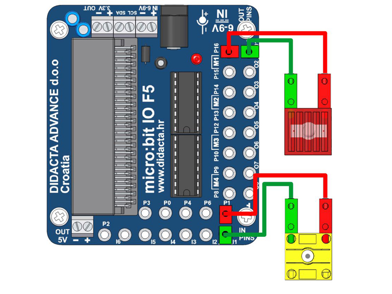
Connect the RED light to OUT 1 (P16), GREEN to OUTPUT 2 (P15), ON to OUT 3 (P14), and COLOR sensor to input 1 (P1). Connect the sensor power to the OUTPUT P8. Add "digital write pin P8 to 1" on start after "led enable". Use the analogue reading of the input value in the program.
Set the program's operation according to the Input Readings for color matching.
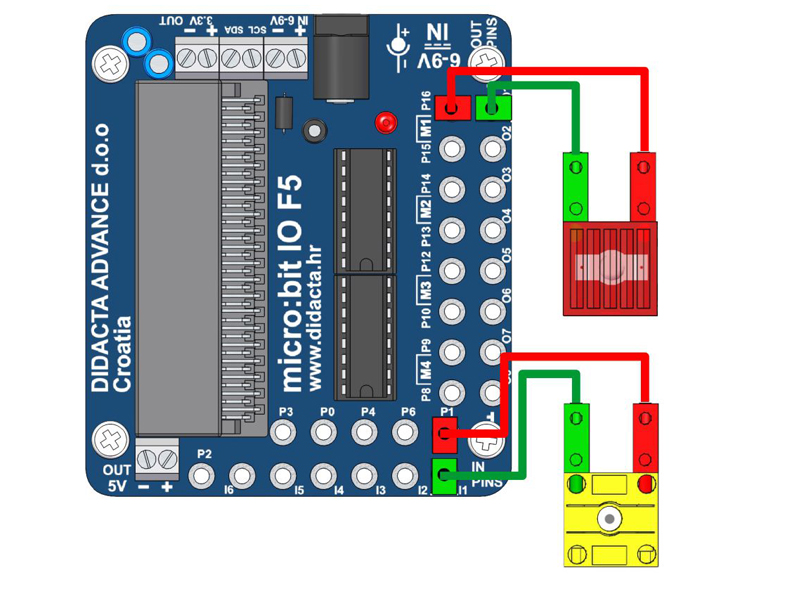
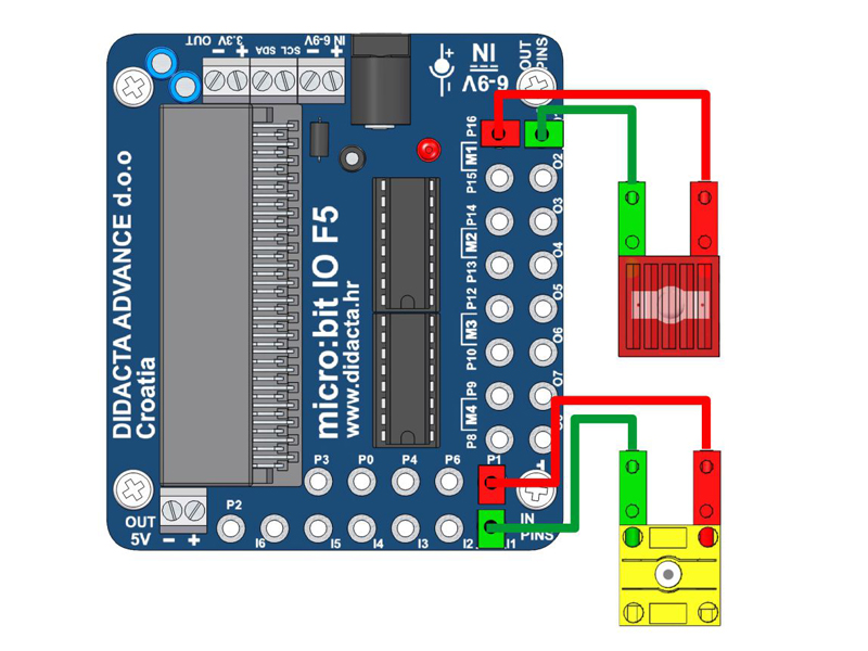
LIGHT CONTROLL - POTO sensor (ANALOGUE) - RECOGNIZING BLACK LINE
Connect the RED lamp to OUT 1 (P16), and the PHOTO sensor to input 1 (P1). Use the analogue reading of the input value in the program. Base should be illuminated. You can do a test by turning the sensor towards the light.