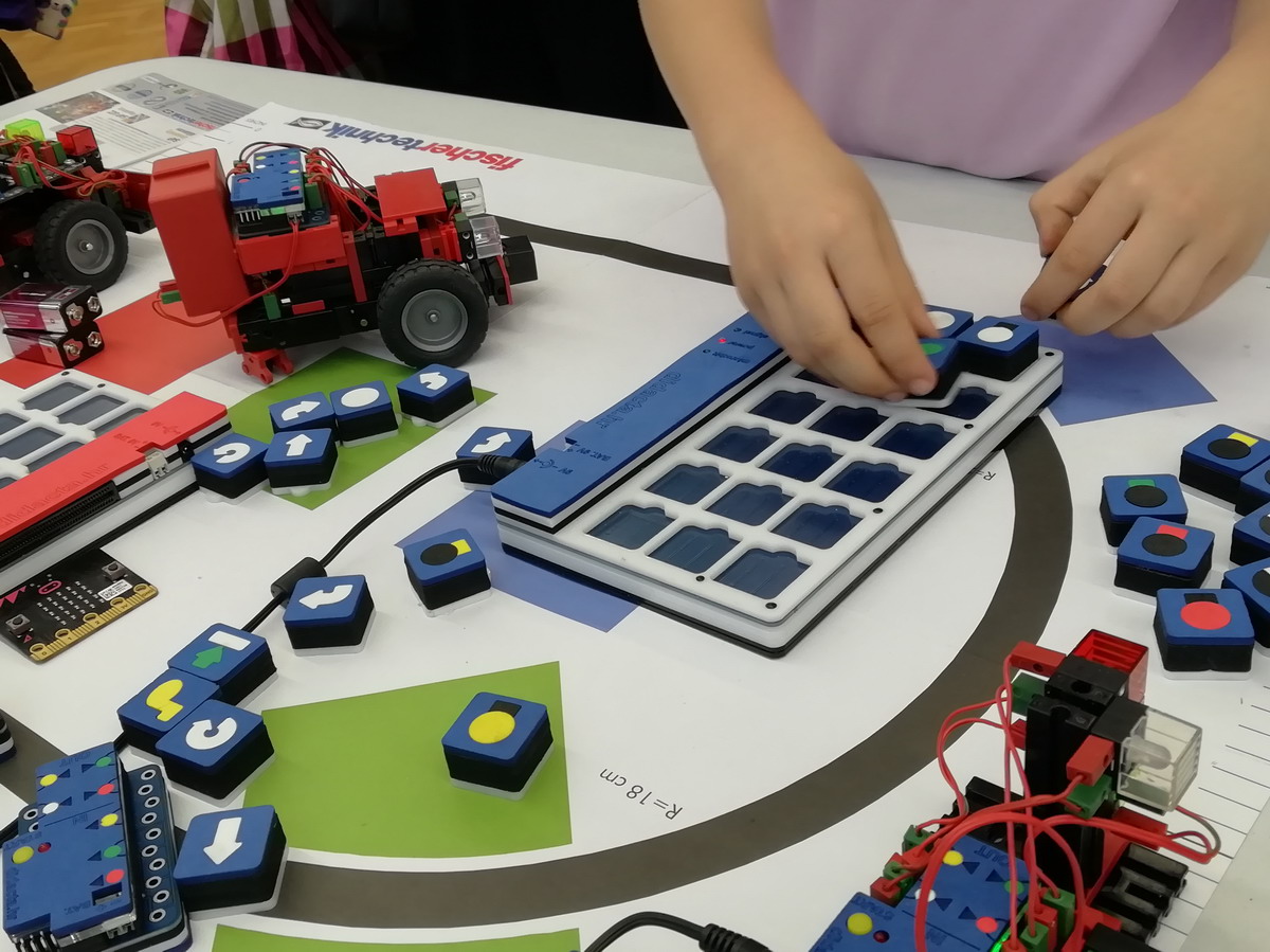
| | | PROJECT IN WORK | | | | | | The set is intended for children aged 5-7 years.
The goal is to learn to solve more complex problems (by disassembling them into parts - objects) and with logical thinking to learn the basic steps of programming, construction and robotics.
The child's focus is directed to a part of the problem - a single object or related objects.
Objects are all active parts of a model that can be controlled via a control module. Objects can be input (connected to the input of the receiving module) and output (connected to the output of the receiving module).
Two programs can be arranged for each input object. One program is for the state when the input object has a signal (ON), and the other for the state when the input object has no signal (OFF). Such programs are called object programs. In addition to object programs, the states of output objects can also be controlled through the main program. | |
|
|
| | | | ProgBlox tablet |  | | | | | We have completed a new version of the tablet with a built-in lithium battery. Autonomy of work more than 4 hours. Tablet weight 265 grams, dimensions 210 x 135 x 10 (18) mm. | |
|
|
| | | DEVELOPMENT PHASE | | | 10.03.2023. The idea for the product was created ten years ago, and the final version last year.
Unfortunately, due to the unavailability of some electronic parts and other materials, the project took longer than planned.
The first test version was shown at Maker Faire 2022 in Zagreb.
We are now in the phase of creating a battery-powered ProgBlox pad and defining the different models that will be part of the set. | |
|
|
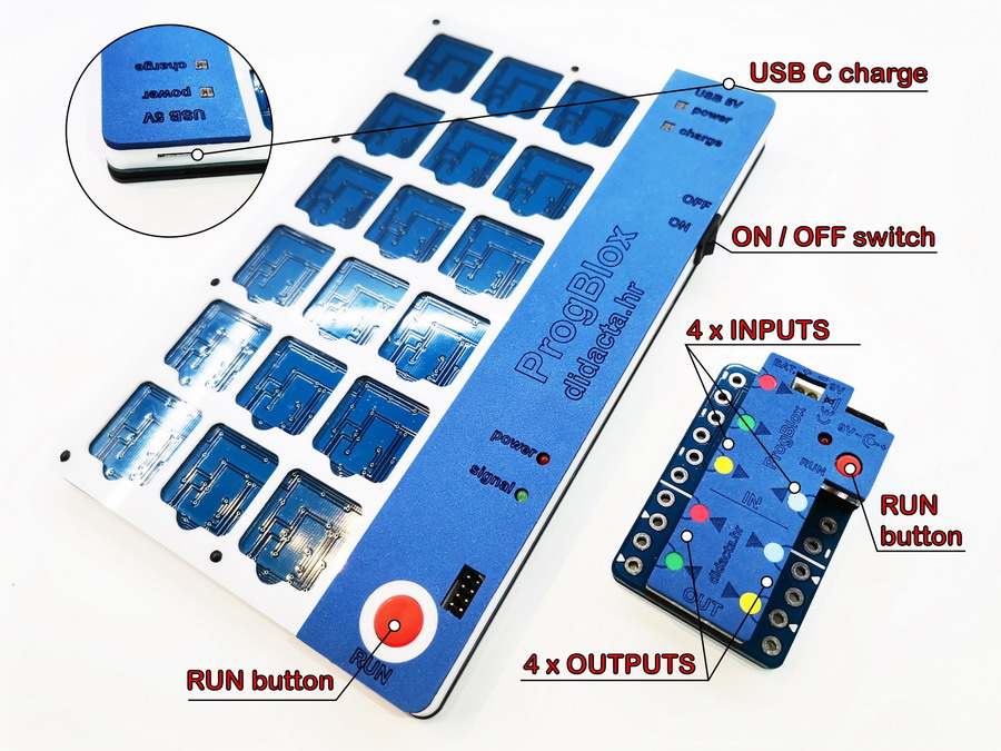
| | | TECHNICAL DESCRIPTION - tablet and control module | | | | | | The ProgBlox pad is used for stacking programs. Programs can have a maximum of 18 blocks. After the program is compiled, the RUN key is pressed to send the program to the control module. The tablet is powered by a battery and can work for 4 or more hours (depending on the size of the battery). The battery is charged via the USB C port (5V). The control module can be powered by a 9V battery or an adapter. The module has 4 x digital inputs (signal + GND), 4 x outputs for motors or other devices. The output power supply is approximately equal to the input power supply of the control module (9V). Various sensors can be connected to the inputs of the control module (photo, IR, magnetic, thermal, switch, ...). The module inputs support a voltage of up to 9V. | |
|
|
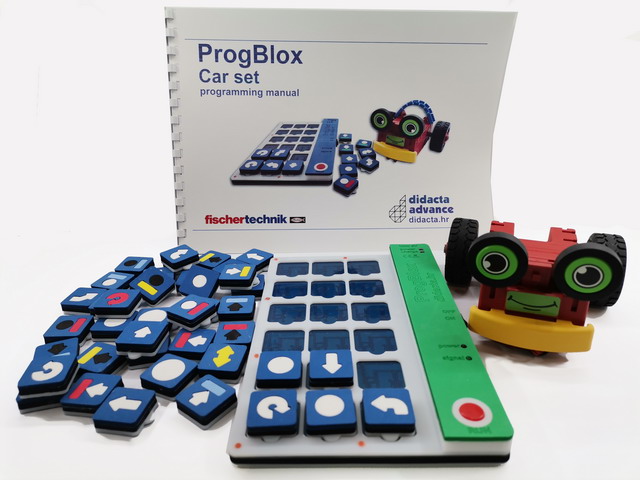
| | | ProgBlox Car set | | | | | | The first complete set, intended for the youngest programmers. The set consists of a robotic car that has touch sensors (bumper) and IR sensors. Sensors can be used to control car movement. In addition to the sensor, the multi-colored LED light can also be controlled by program. The set contains 56 command dice. | |
|
|
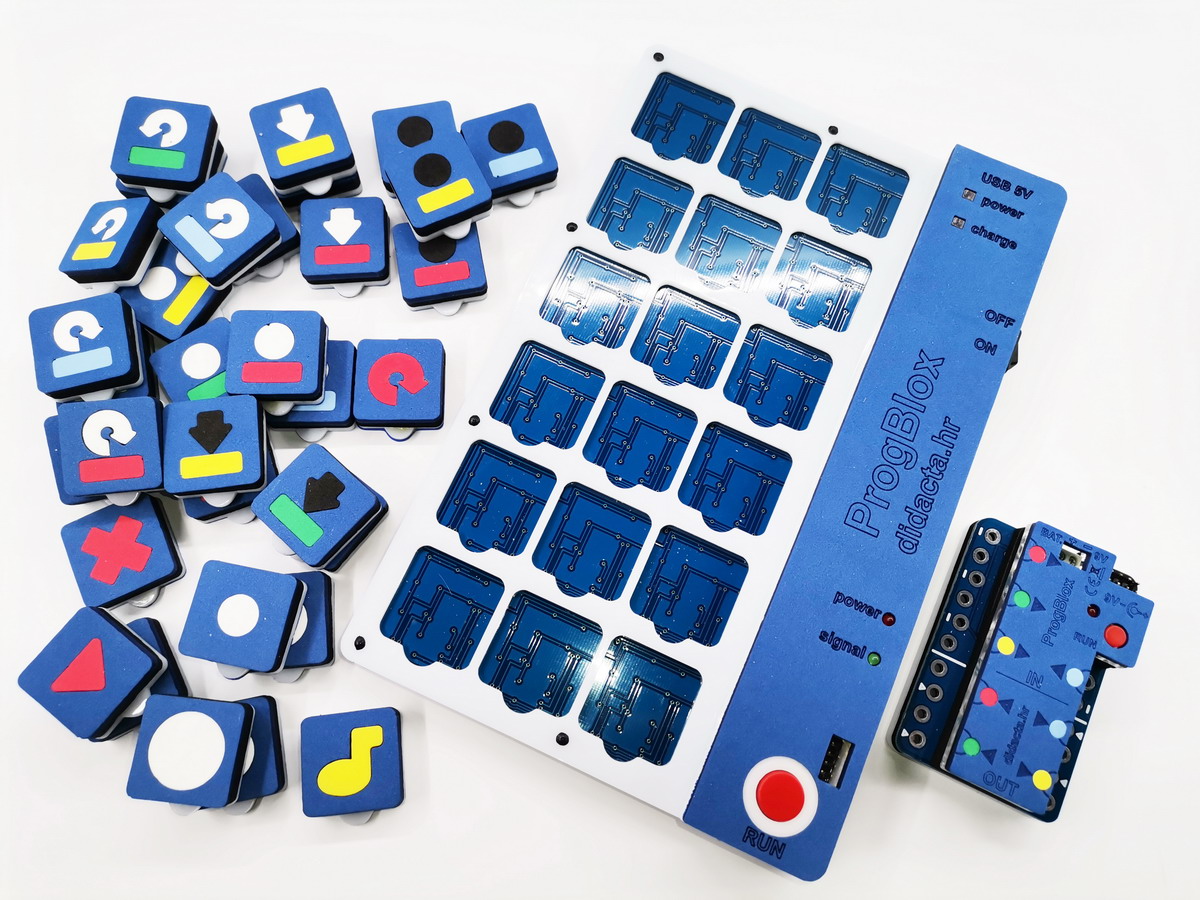
| | | ProgBlox BASIC set | | | | | | The ProgBlox starter ( BASIC ) set consists of a ProgBlox tablet, one control module and 40 programming blocks. The tablet has a 600 mAh battery that enables autonomy of work for about 4 hours. Extensions of the set make it possible to control the vehicle or several control modules via a single tablet. | |
|
|
| | | How to program | | | | | | We agree with the left to right to the right, and the starting position is the first lower on the left. A short program consisting of a maximum of six software cubes can also agree on vertical. The video shows both of the program stacking ways. Once the program is complex, the RUN button is pressed. | |
|
|
| | | Object program and main program | | | | | | Example of object and main program. The first program defines a "switch" object. When the button is pressed, the GREEN light turns on. The second - the main program, defines what happens with the yellow light. | |
|
|
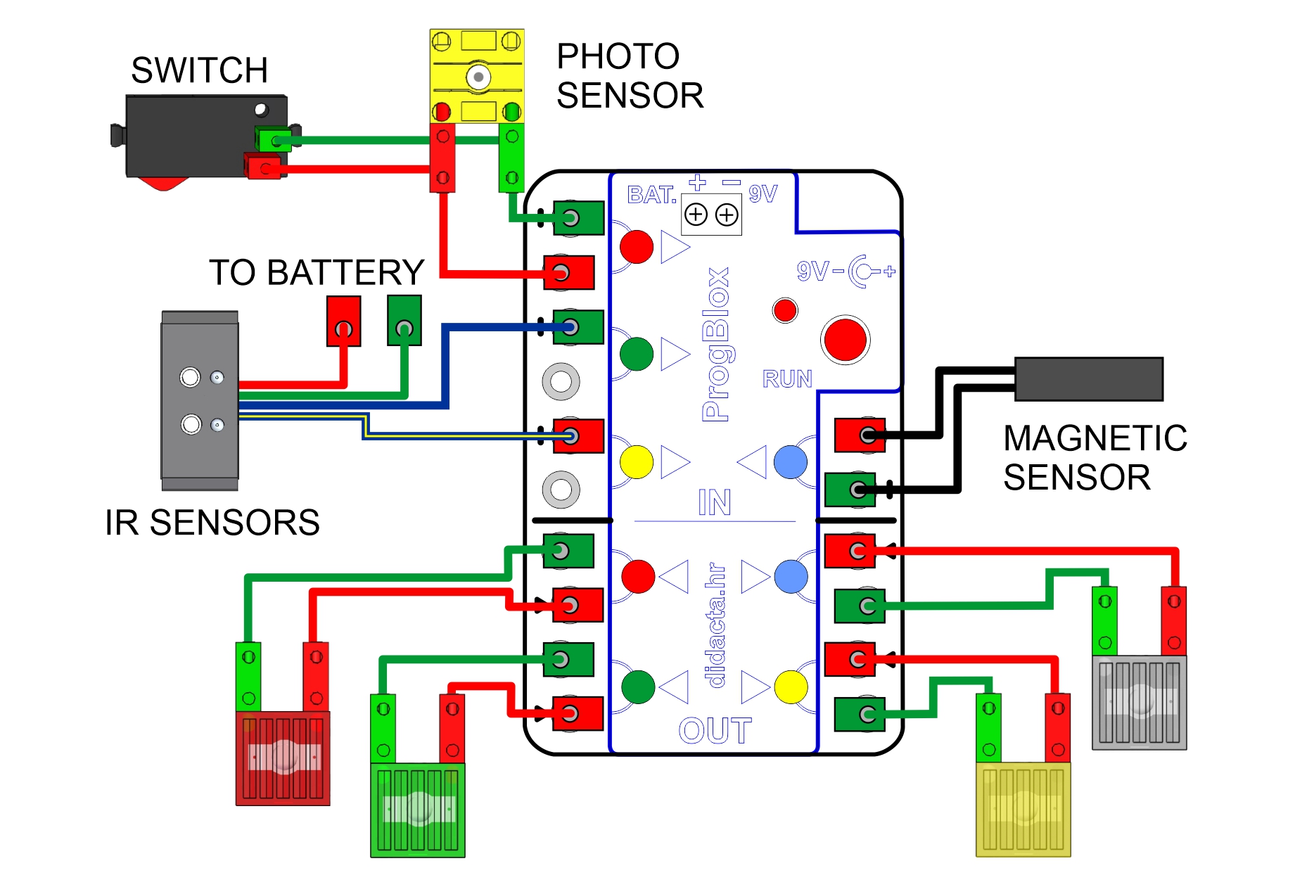
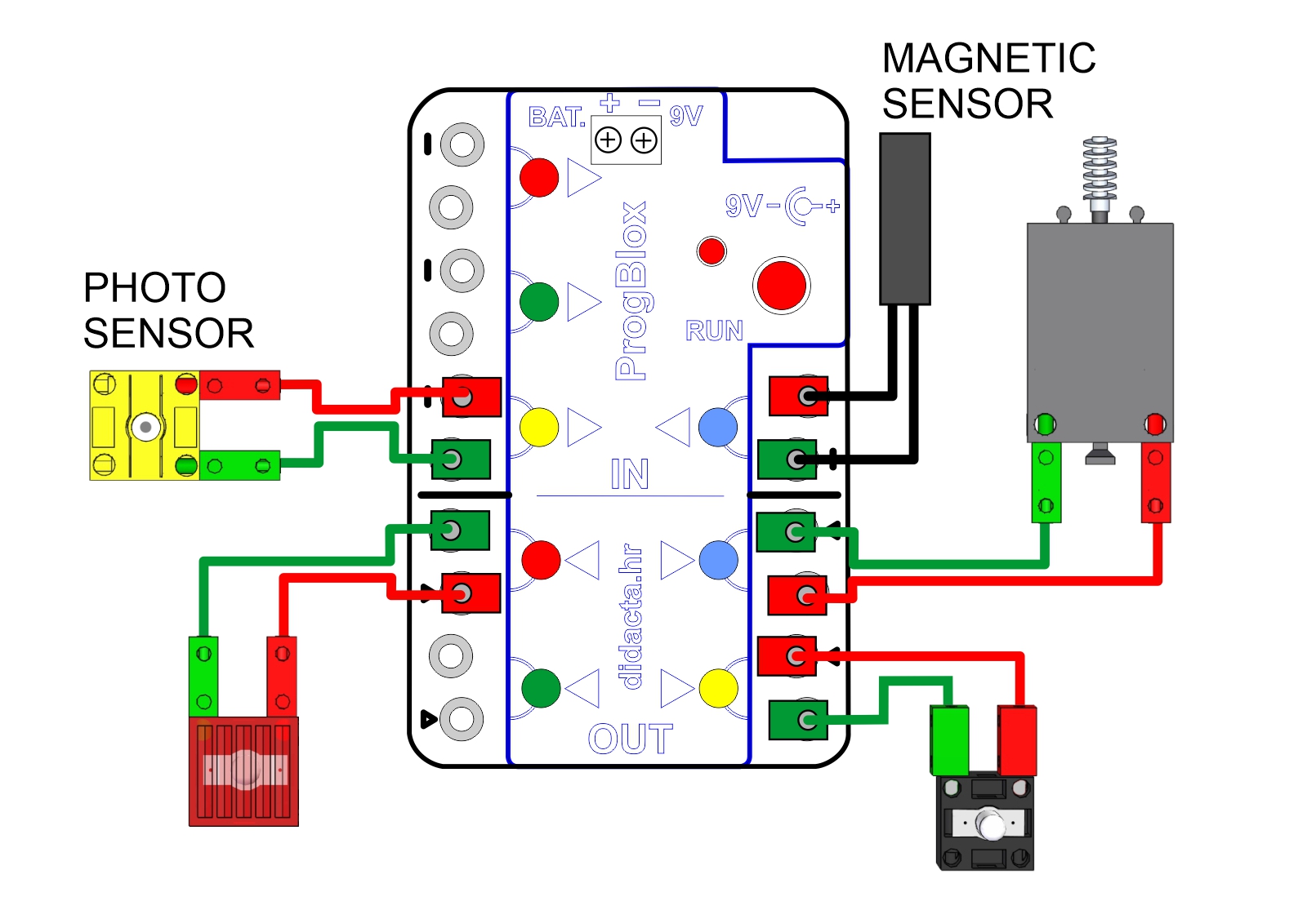
| | | Which sensors can be used? | | |
| |
| | All digital and analog sensors can be used. Analog sensors will work like digital ones. In the example, PHOTO, magnetic, switch (touch) and IR sensor were used. | |
| |
|
|
| | | Model - Trafic lights | | |
| |
| | An example of the main program for simulating traffic lights. | |
| |
|
|
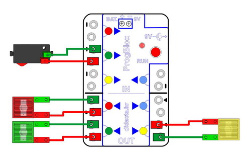
| | | Model - Hand dryer | | |
| |
| | Main program: lights up (yellow output). The first object program for the photo sensor defines: when the NEMA signal turns on the motor ventilates (blue output). Another object program for the photo sensor defines: when IMA signal turns off the fan motor (blue output). | |
| |
|
|
| | | Hand dryer + signal light | | |
| |
| | Main program: lights up (yellow output). The first object program for the photo sensor defines: when the NEMA signal turns on the RED light (red output) and the motor | | ventilates (blue output). Another object program for the photo sensor defines: when IMA signal turns off the RED light (red output) and the fan motor (blue output). | |
| |
|
|
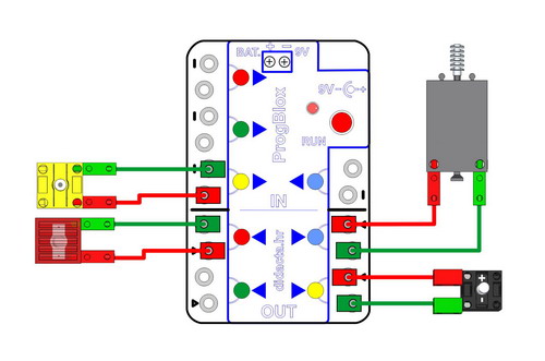
| | | Model - Useless machine | | |
| |
| | The purpose of the useless machine model is to turn off the light. Through the button (red input), the RED light (red output) lights up. When the PHOTO sensor (green input) has a signal, the engine | | starts. The motor turns on the button (yellow input) via the lever. When the button (yellow input) has a signal, the RED light goes out and after half a second the engine is turned off. | |
| |
|
|
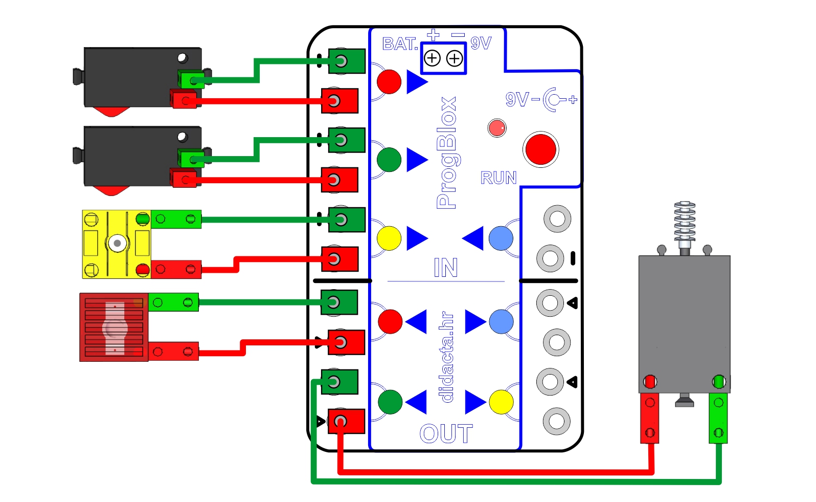
| | | Model - Barrier with signal light | | |
| |
| | Ramp model with RED signal light. The ramp is raised when the PHOTO sensor signal is interrupted (YELLOW input). The ramp goes up, stays up for a certain amount of | | time and then goes down. When the ramp is lowered, the RED light (RED output) lights up. Ramp raising is also activated via the MAGNETIC sensor (BLUE input). | |
| |
|
|
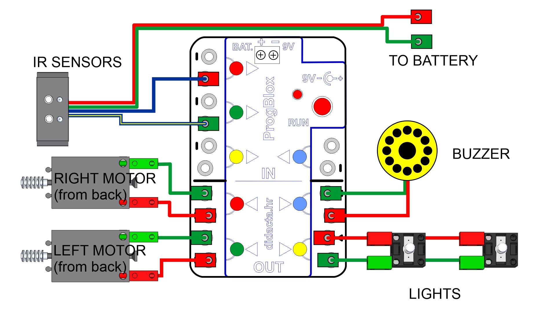
| | | The vehicle follows the line - save program | | |
| |
| | Programming the vehicle to follow the line via the IR sensor (RED and GREEN input). The power supply of the IR sensor is connected to the battery (9V). The vehicle has a "SIREN" (LIGHT BLUE output) which can be switched on if | | desired. In addition to the siren, lights (YELLOW light) can also be activated on the vehicle. At the end of the video example, the "SAVE" block is used, which saves the program in the memory of the application module. | |
| |
|
|
| | | The vehicle follows the line - load program | | | | | | After connecting the power supply, pressing the button (RED) of the receiver module loads the program and the vehicle is ready to follow the line. | |
|
|
|
|
|
|
|
|
|
|
|
|
|
|
|
|
|
|