In the first part of the instructions for programming the micro:bit AD BW interface, the initial steps are covered. Connecting and starting the interface, loading the library and all the basic functions (printing text, lines, circles, circles, rectangles, ...). The second part deals with how to use SCROLL functions. The third part contains all the graphical functions that can be used to create different games. The instructions are in PDF format and can be copied via the DOWNLOAD button on the preview (DOWN ARROW).
Display the status of the mobile robot sensor (display AD) - 02
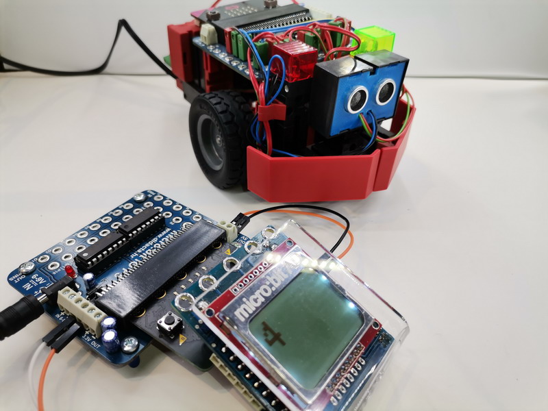
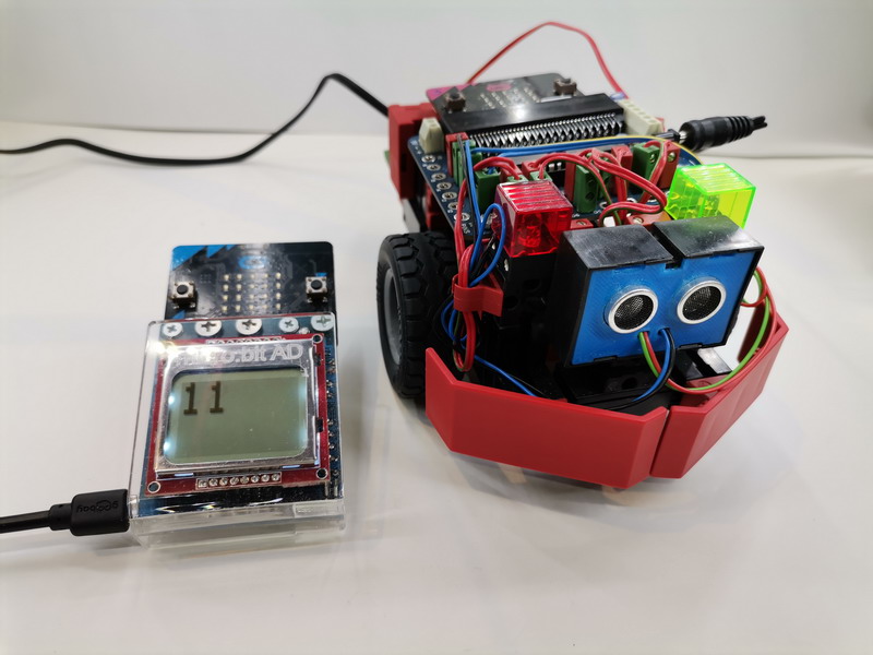
We can use a radio connection to display the read values of the sensors located on the mobile robot. We send the read value of the sensor via radio connection to the micro: bit with the display (wires or screws). In order for this communication to work, it is necessary to add radio communication commands to the program that controls the operation of the model. The example shows the added commands for reading the ultrasonic sensor (according to the example in the ROBOTIC SET). The receiving program needs to be loaded into the micro: bit with the display only once.
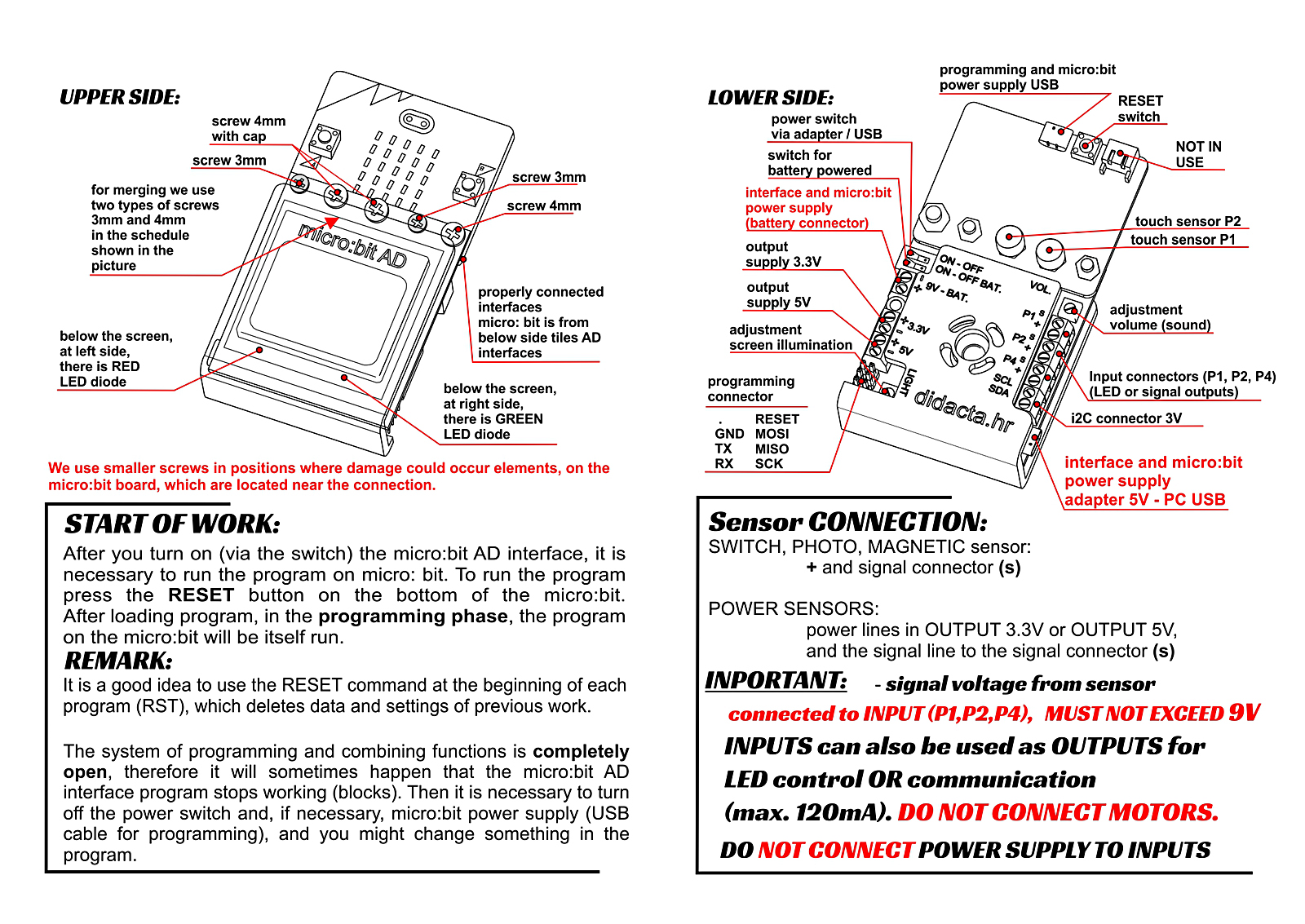
This example shows the AD display connected to the I2C and 5V (to the display battery connector) connectors on the F5 interface. Micro: bit is in F5 interface.
Display the status of the mobile robot sensor (display AD) - 01
We can use a radio connection to display the read values of the sensors located on the mobile robot. We send the read value of the sensor via radio connection to the micro: bit with the display (wires or screws). In order for this communication to work, it is necessary to add radio communication commands to the program that controls the operation of the model. The example shows the added commands for reading the ultrasonic sensor (according to the example in the ROBOTIC SET). The receiving program needs to be loaded into the micro: bit with the display only once.
SENDING MESSAGES TO SECOND micro:bit
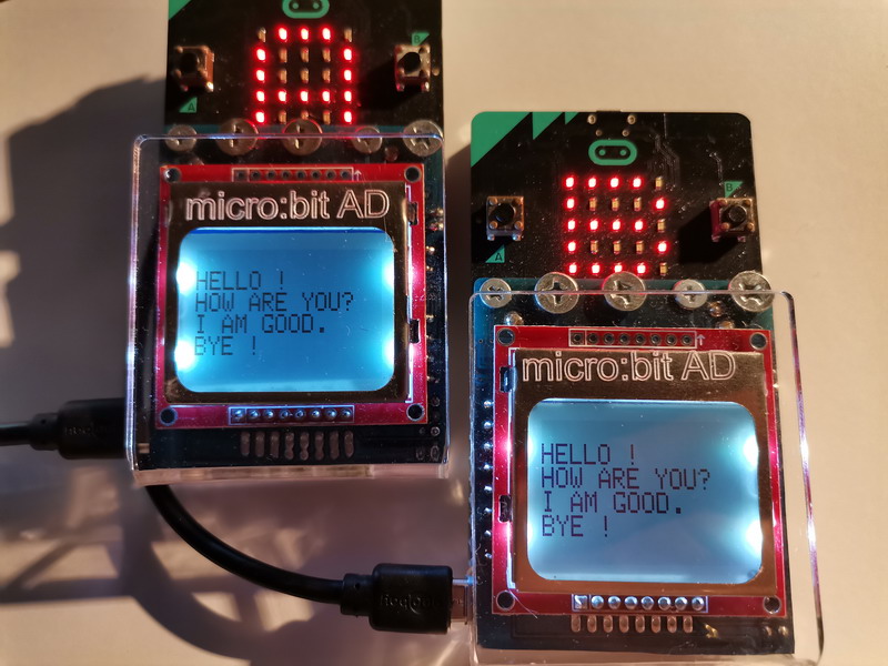
Example of sending (A) messages wirelessly to one receiving (B) micro:bit. What are all the potential communication options between multiple micro:bits? Send and receive messages from one or more devices.
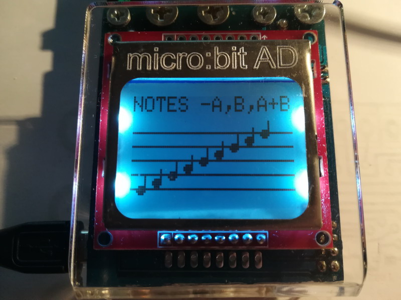
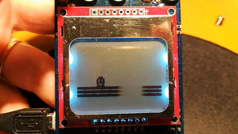
MUSIC NOTES
An example that prints musical notes on note lines while performing a specific tone.
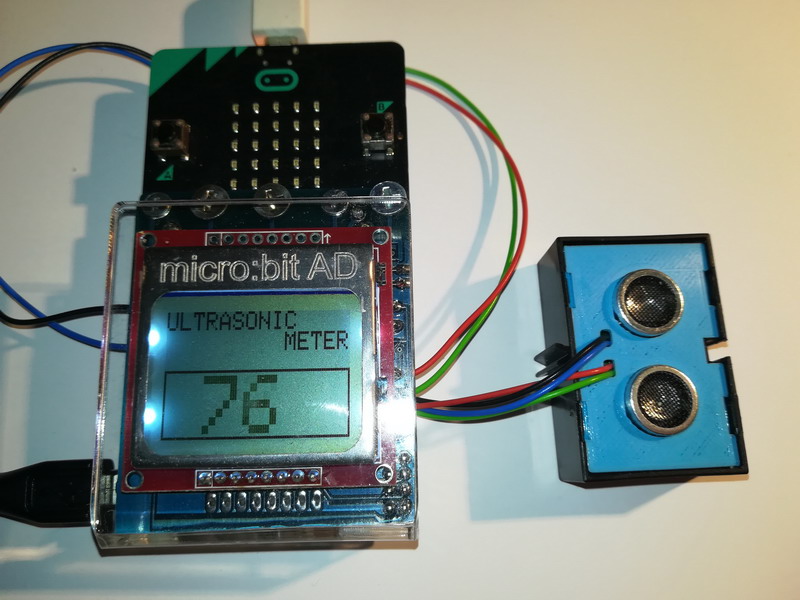
ULTRASOUND METER
Distance measurement via ultrasonic sensor. Example of distance measurement with value printout on micro:bit AD display. The sensor is connected to pins P1 and P2, and to the 3.3V power supply.
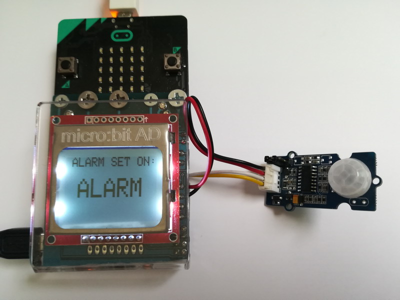
ALARM
In this example we use a GROVE PIR sensor and read pin P1 analog. When the pin has a value greater than 100, the alarm sound and warning are turned on, and when it is lower, it is turned off. The sensor detects changes up to a distance of 6m. The sensor is connected to pin P1 and 3.3V power supply.
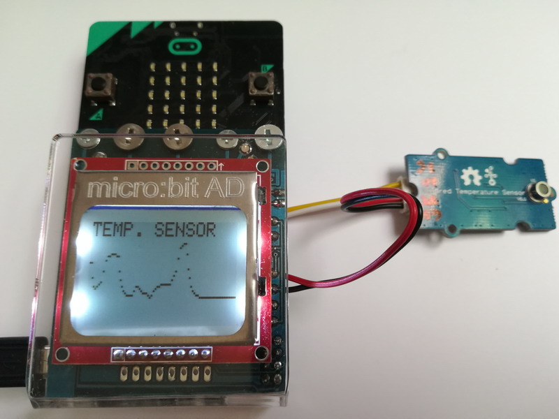
TEMPERATURE MEASUREMENT GRAPH
Simple temperature measurement graph. The example is with relative measurement and for exact values we should add recalculation (calibration) in the program. In the example, a thermal sensor is used for remote temperature measurement GROVE, which is connected to pins P1 and P2, and to a 3.3V power supply. An analog reading of pin P2 is used for the graph. According to this example, graphs of readings can be made from different sensors with analog values (photo, thermal, sound, resistant, ultrasonic, ...).
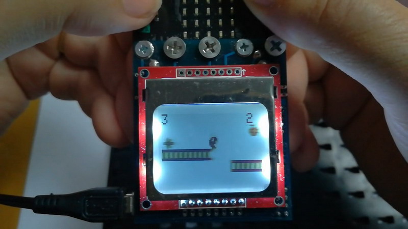
COMPLETE GAME WITH TWO PLATFORMS (SCREEN)
Example of a game with two platforms and four objects - a total of six on two screens (max.20). All the main functions and parameters that need to be set can be seen in the program. There are other functions that affect the game and can be used, such as the automatic level change (LEVELA) of the game. From initial speed (slower) to increasing speed. Control of the player object via the A key on the micro: bit (JUMP).
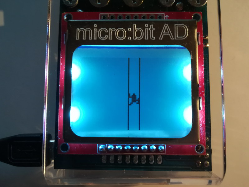
PLATFORM GAME - BEGINNING
In just EIGHT STEPS (we add more one feature), the basic construction of the platform game is set. This basic example shows how to create an object, a platform, and certain game features. The player is controlled via the A key on the micro:bit.
GRAVITY AND COLLISION
Touch sensors change screens, and keys A and B control the horizontal movement of a player's object. In this example, we use the GRAVITY and COLLISION functions to control the player object. Test how a player object moves with the GRAVITY feature turned on, and how it affects the environment when the COLLISION feature is turned on or off.
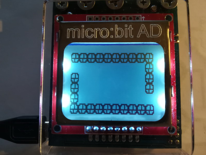
CREATION OF INACTIVE OBJECTS (WALL)
Objects that do not actively participate in the game, such as walls, can be defined up to a length of 10 bitmaps in the horizontal or vertical direction. All in all there can be 20 objects (active and inactive, except players) defined in the game. During the game, objects can be redefined.
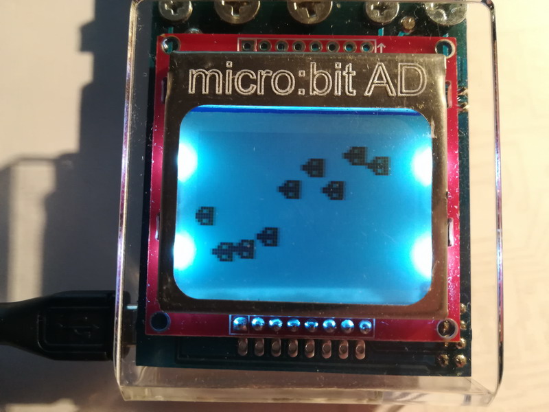
HORIZONTAL SHIFT OF OBJECTS - GAME SCROLL - SPEED
Example of horizontal movement of multiple objects on the screen via the GAME SCROLL function. The program draws objects to the vertical (y) position via the RANDOM function. The horizontal position is the same for all objects (x = 70). The contents of the screen automatically scroll by one pixel. In order for new objects to appear on the screen at some distance, the variable index2 is used. The example shows how to control the feed rate using the GAME SPEED function. The higher the value, the lower the value and the higher the number of offset pixels (2). When deciding on the speed of movement, the number of objects on the screen (active) should be taken into account, which affect the player's object and the communication between the micro: bit and the display. The maximum speed is "10" and the minimum is "255". If high speed is used with a lot of objects and functions that use communication, the program may stop working.
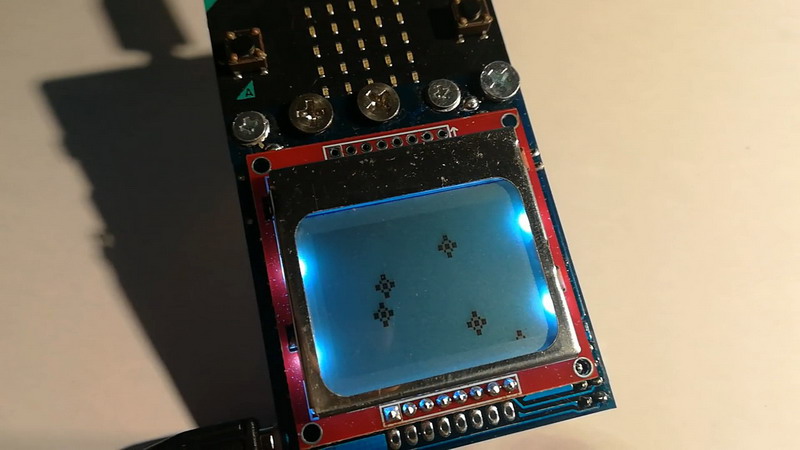
VERTICAL OBJECTS SCROLL
Example of moving multiple objects on the screen via the SCROLL function. The program draws objects to the horizontal (x) position and the initial vertical position (y = 0) via the RANDOM function. Then the entire contents of the screen are scrolled eight pixels down.
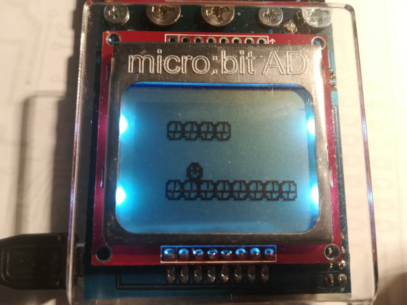
OBJECT CONTROL - PLAYER
The player object can be controlled via the buttons on the micro: bit (A and B) and analogously via inputs P1 and P2. The example shows the control program in all four directions. In addition to controlling the movement of the object by a few pixels, the player's object can jump. We will show this control in another example.
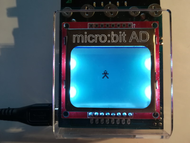
ANIMATED PLAYER OBJECT
The animation is done by simply defining a second bitmap (animation bitmap) that alternates with the main bitmap. The animation speed can be adjusted via the command (animation player speed). The setting must be set for a game that uses a horizontal scroll (GAME scroll).
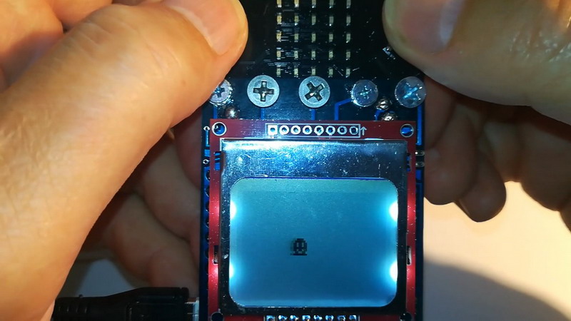
CREATING A PLAYER BITMAPE
Example of creating a bitmap of a player object. The player's object can be controlled via the "A" and "B" buttons and analogously to the "P1" and "P2" pins. In a later example, complete control in all directions will be shown.
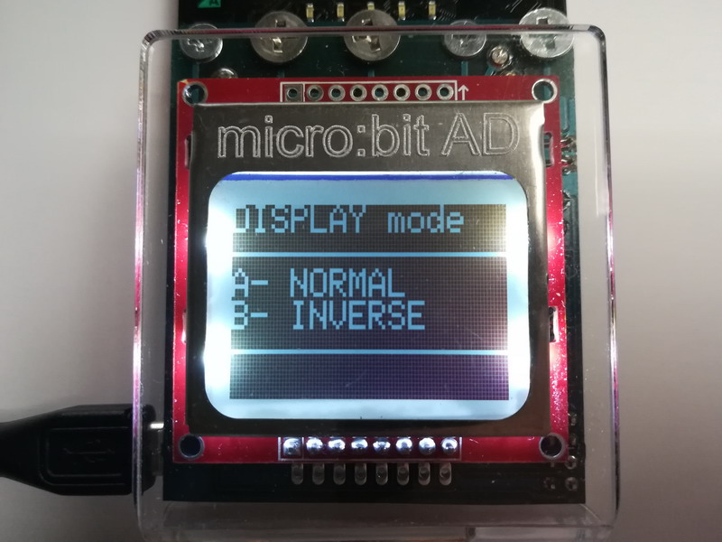
SCREEN MODE - NORMAL - INVERSE
If you want to change the screen display, you can change the standard black and white (0) to the inverse white and black (1).
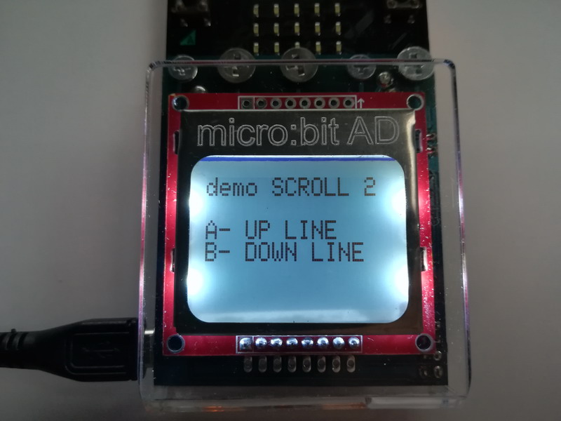
UP OR DOWN (SCROLL)
Text scrolls one line up or down.
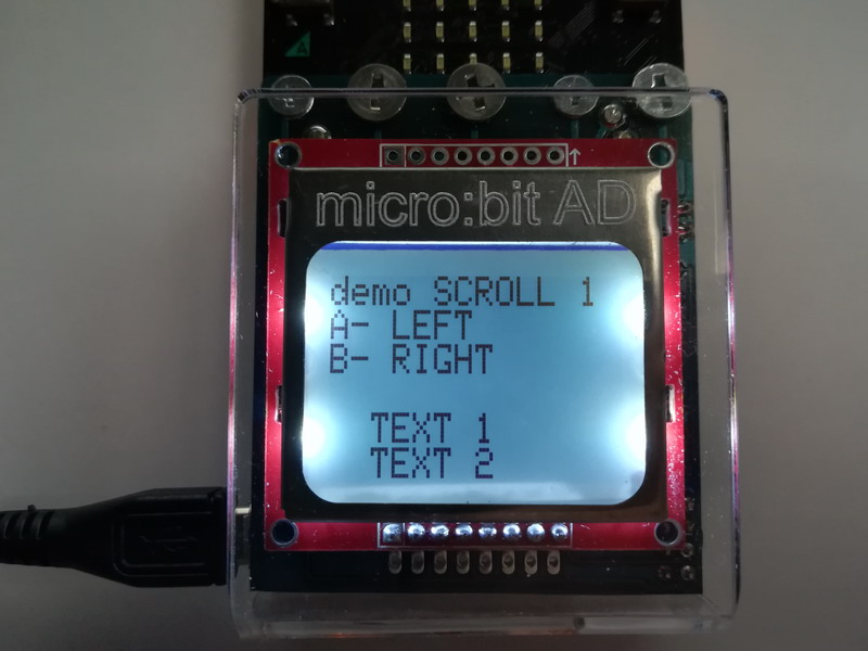
BIT SCROLL - HORIZONTAL
Horizontal, fine, scroll for one or more bits can be defined for one or more lines of text (character mode). If you want to do a full screen scroll you need to specify row 0 as the initial to 5 rows. The scroll can be performed "CIRCULAR" (print on the other side of the screen) or disappear.
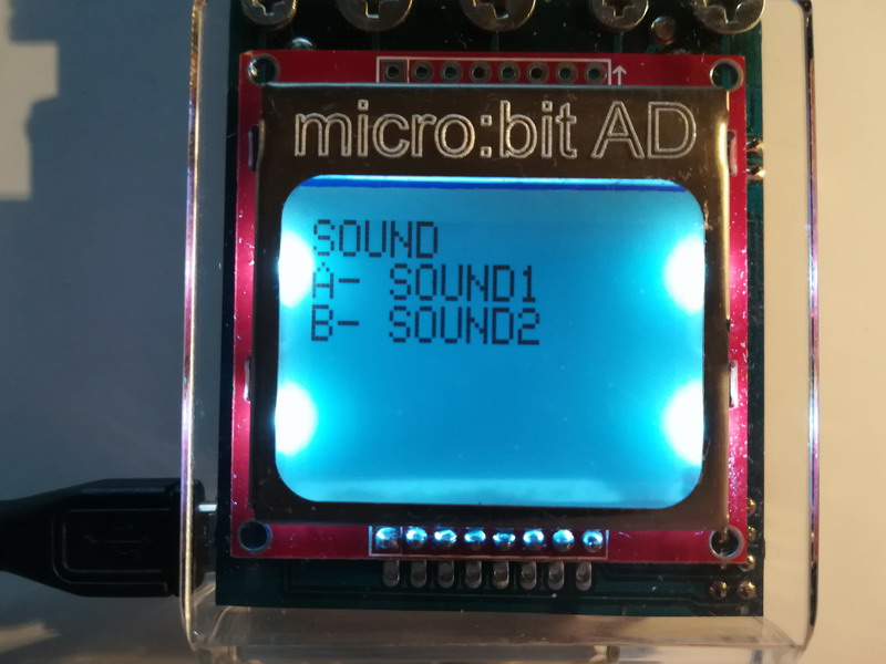
SOUND SIGNAL - BIP
You can generate an audible signal in a specific frequency range 0 - 255 and for 1 second. This sound generates a micro: bit AD interface and does not affect the operation of the program on the micro: bit.
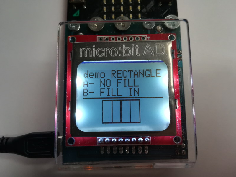
RECTANGULAR - SQUARE
We use the graphic coordinates x (0-83) and y (0-47) to print a rectangle or square.
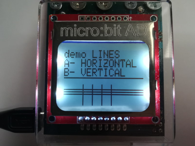
LINES
We use the graphic coordinates x (0-83) and y (0-47) to print the lines.
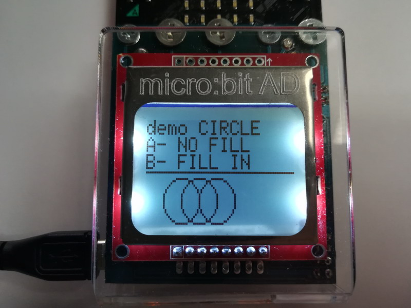
CIRCLE - FILLED CIRCLE
We use the graphic coordinates x (0-83) and y (0-47) to print a circle or filled circle.
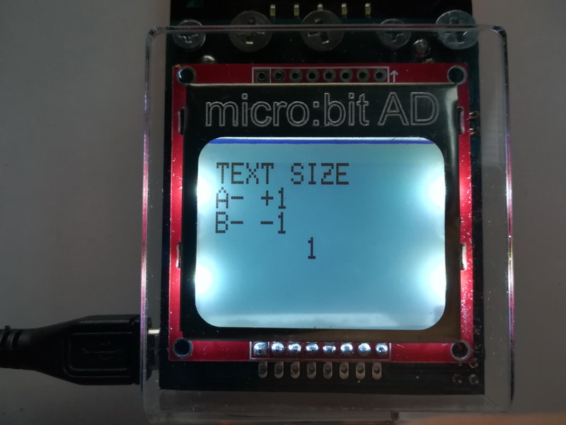
TEXT SIZE (FONT SIZE)
The text can be printed in three sizes (1-3) in character and graphic mode. In this example, we delete the text using a rectangle.
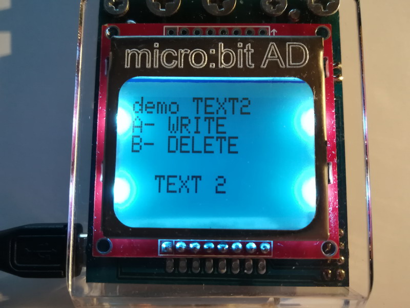
DELETE A CERTAIN TEXT
Deleting text on the screen can be done in several ways. One is by printing a blank line over existing text. The second is to print the same text in "WHITE", and the third is to print a white rectangle with a white fill in the text position.
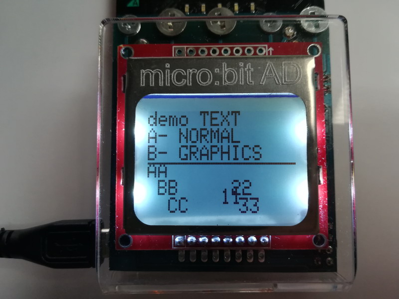
WRITE TEXT ON DISPLAY
Print text on the screen in character mode and graphics. In character mode, text can be printed in 10 horizontal positions and 6 vertical ones. In graphic mode, the text is printed on the pixel position, in 84 horizontal and 48 vertical positions. Printing text in character mode at position x = 2, y = 2 in graphic would be x = 13, y = 17. The size of the characters (font) is 6x8 pixels.