

| PROGRAMMING SCHOOL | RoboPro Coding - TXT 4.0 |
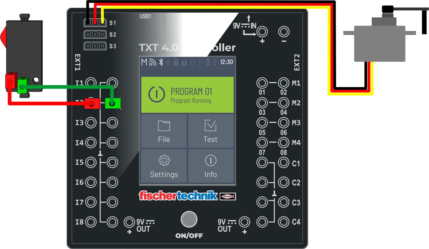
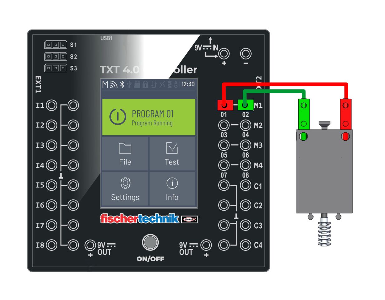
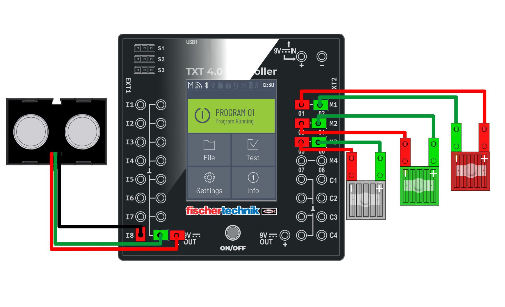
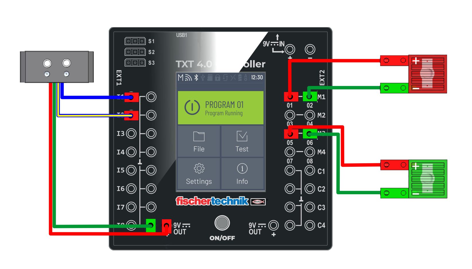
| 1. | SERVO MOTOR | 9. | ULTRASOUND sensor (1.) | ||||||
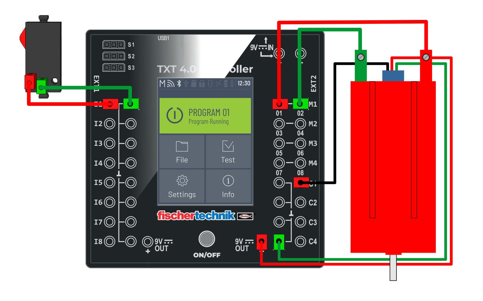
| 2. | ENKODER motor | 10. | IR sensor | ||||||
| 3. | MOTOR - impulse gear | 11. | PHOTO resistor (analog) | ||||||
| 4. | MOTOR speed control | 12. | PHOTO transistor | ||||||
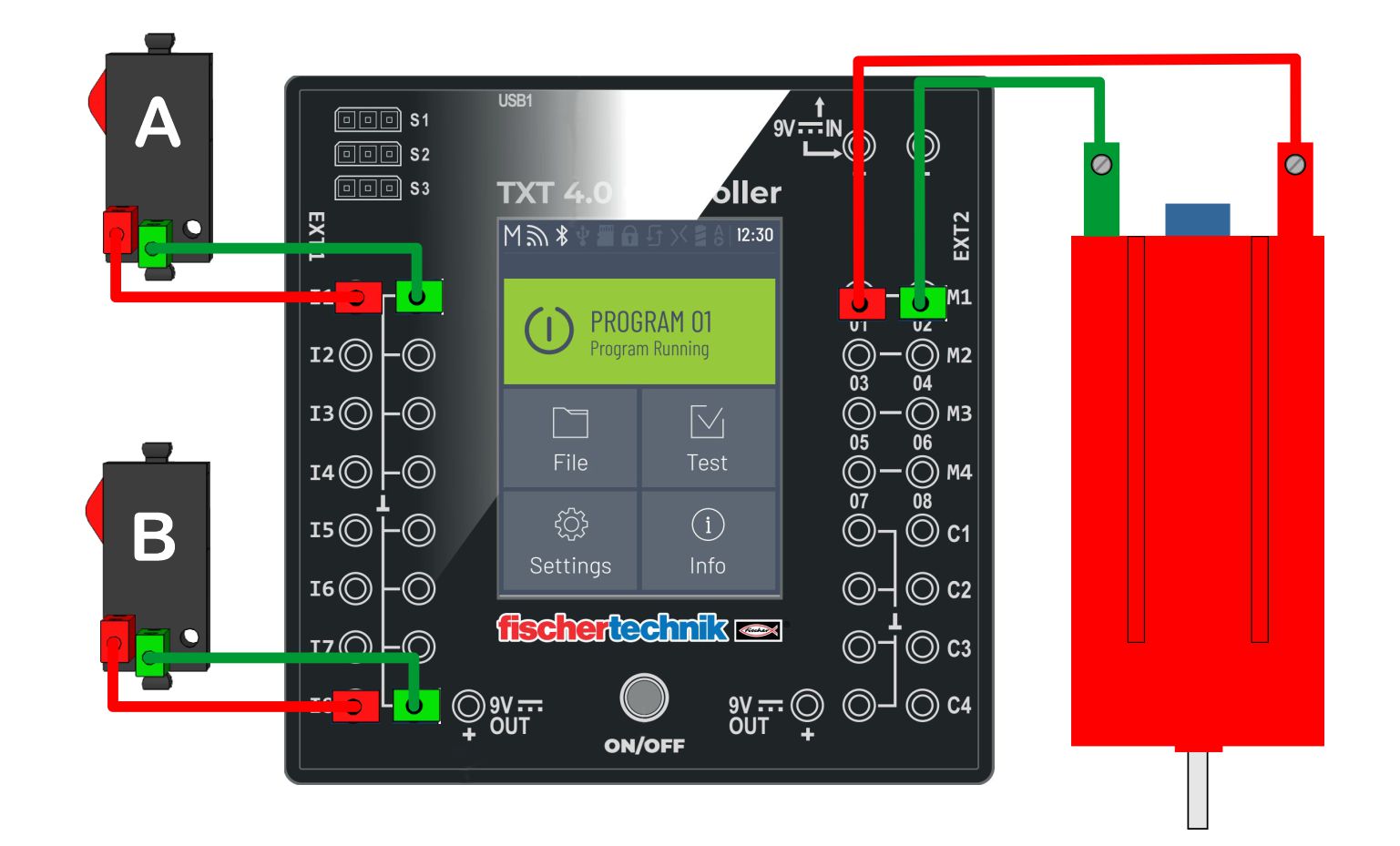
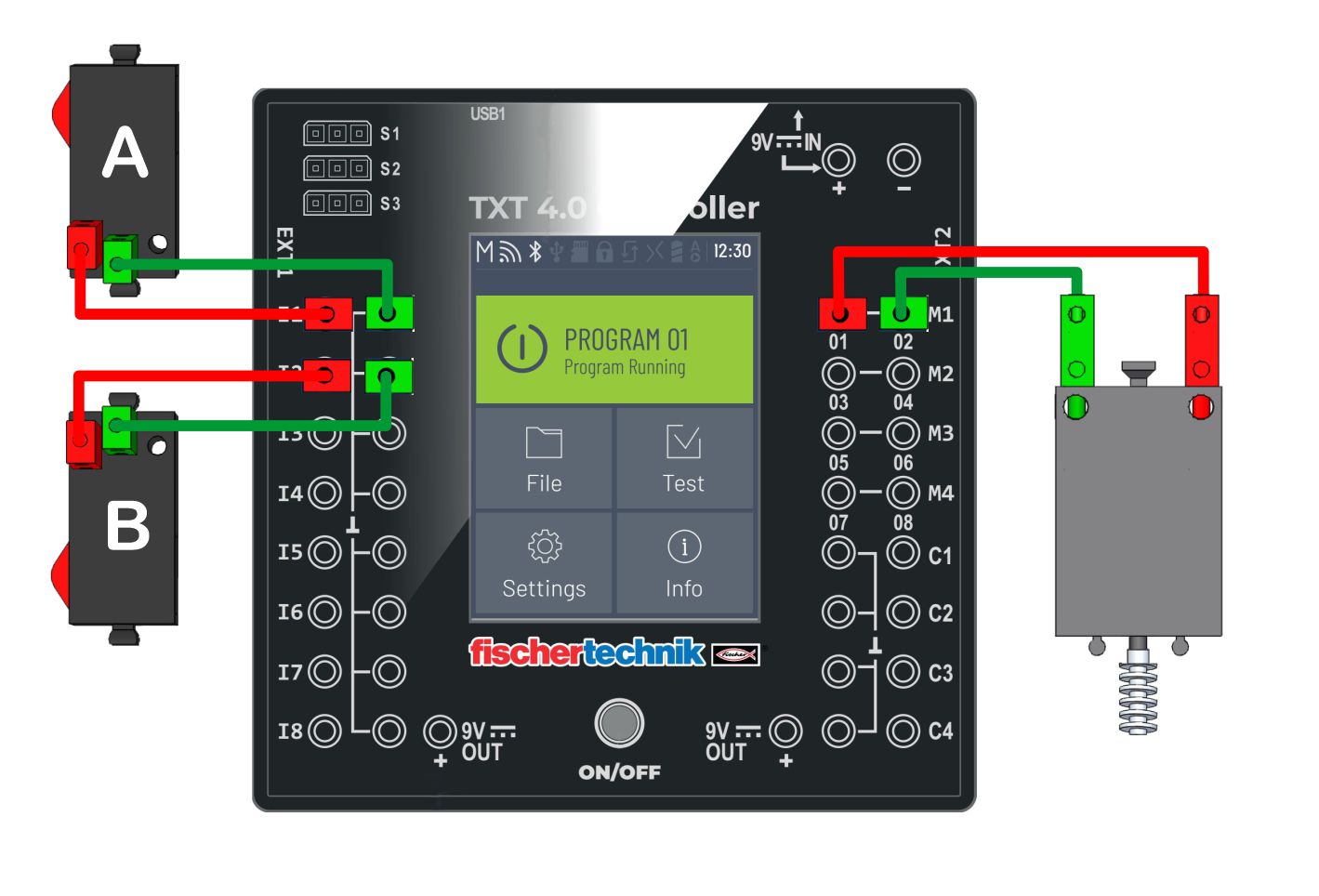
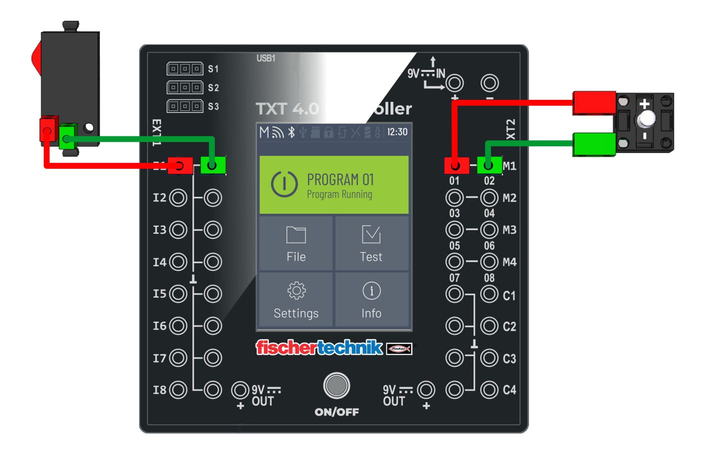
| 5. | MOTOR control with switches | 13. | The LED lights up via a switch | ||||||
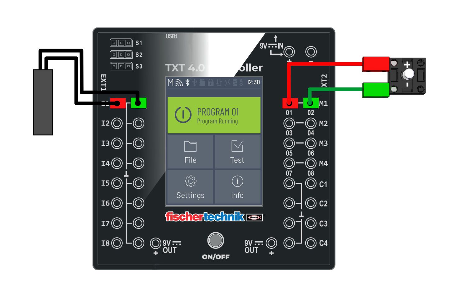
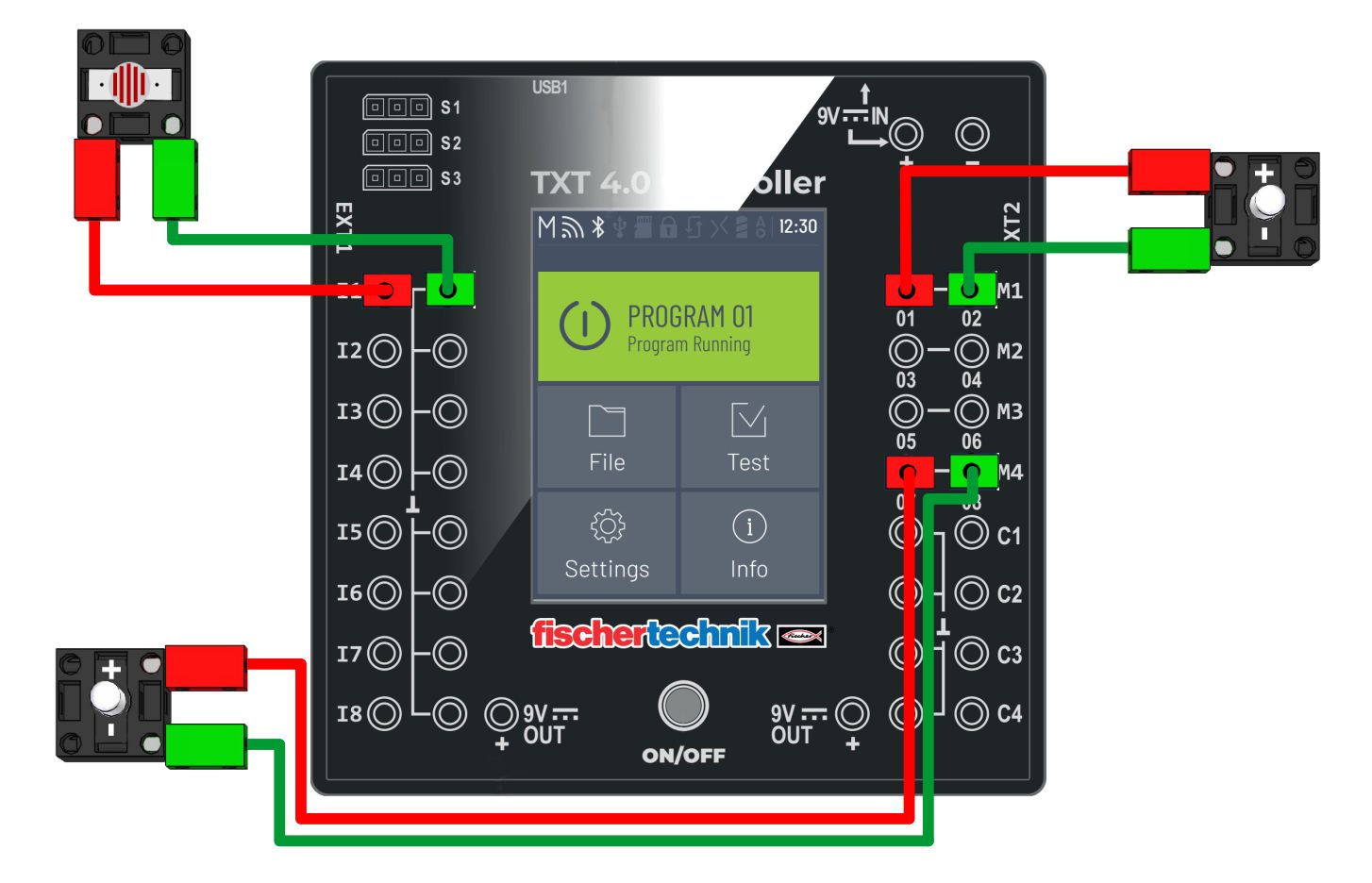
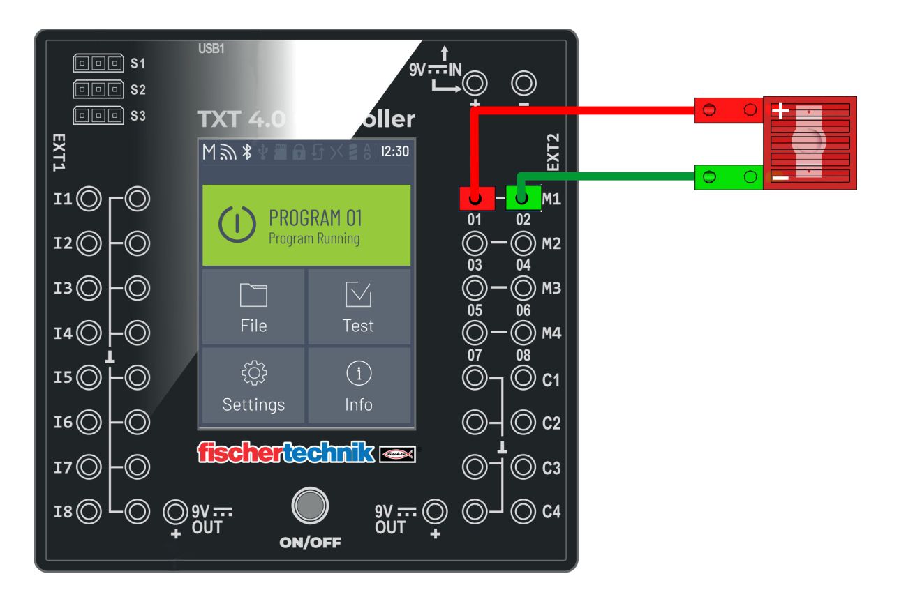
| 6. | MAGNETIC sensor | 14. | Analog LED control | ||||||
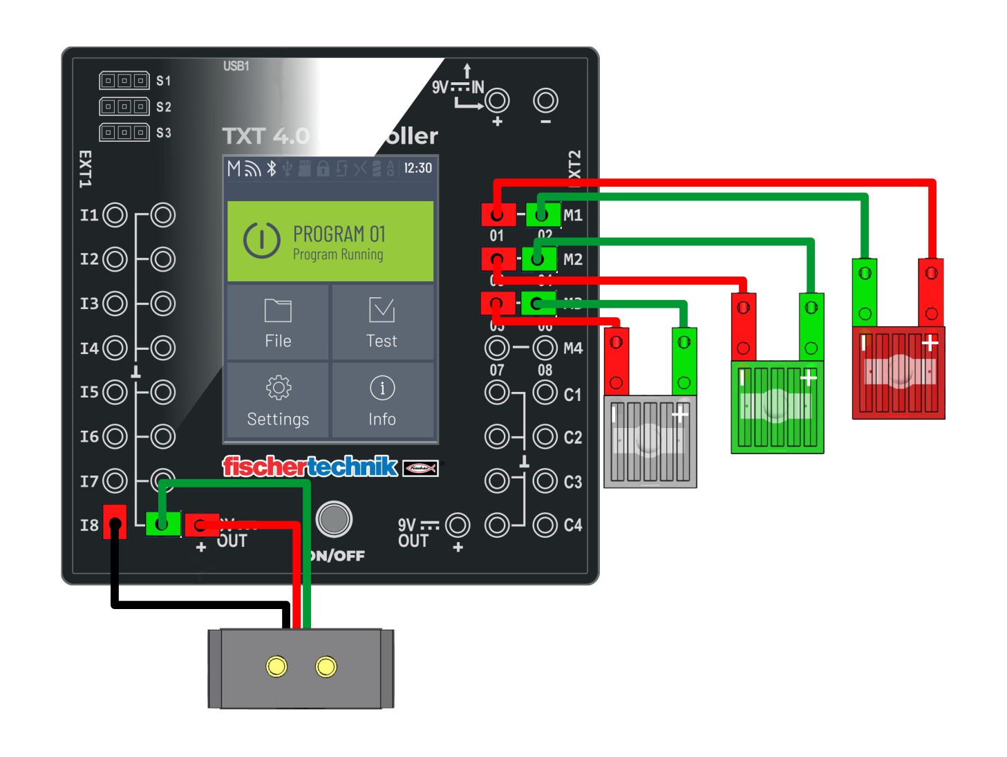
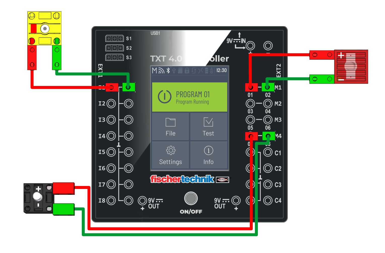
| 7. | COLOR sensor | 15. | Turn on the digital LED | ||||||
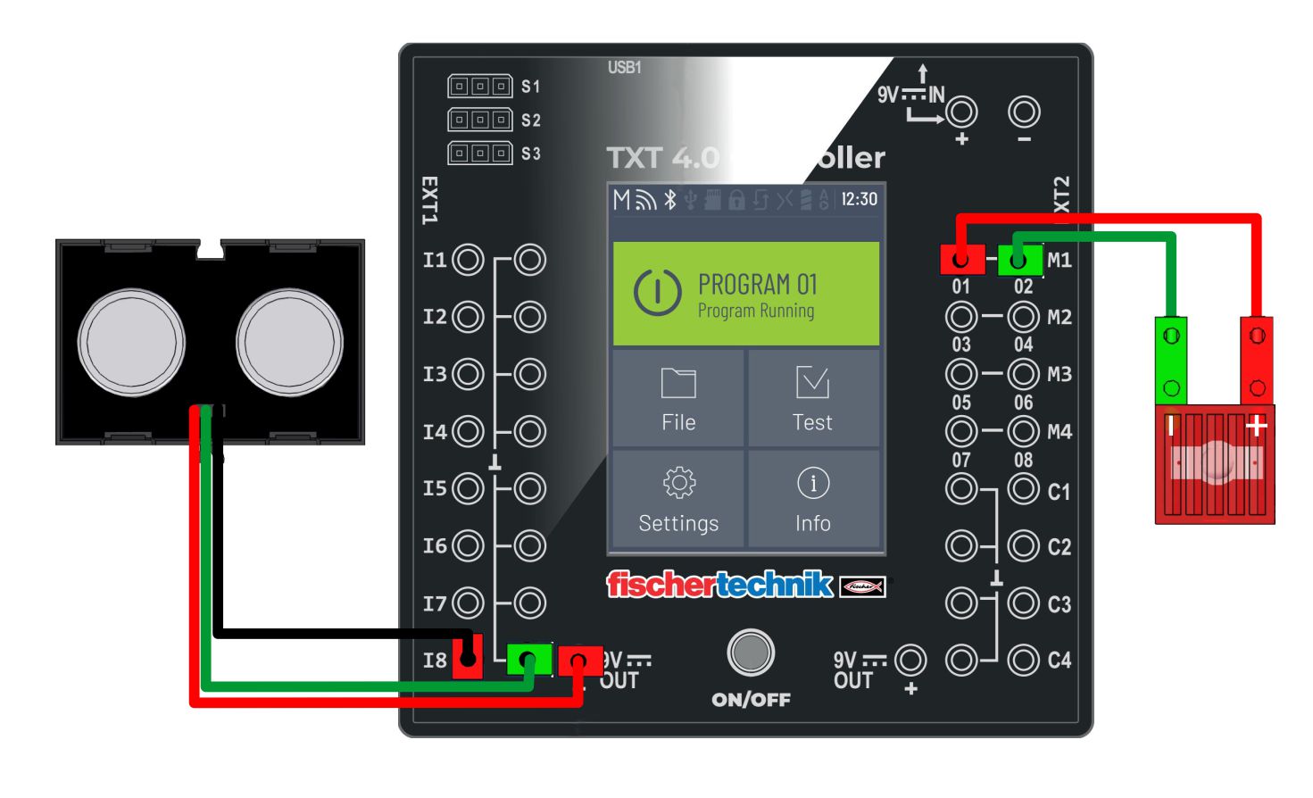
| 8. | ULTRASOUND sensor (2.) | ||||||||
| |||||||||||||||||||||||||||||||||||||||||||||||||||||||||||||||||||||||||||||||||||||||||||||||||||||||||||||||||||||||||||||||||||||||||||||||||||||||||||||||||||||||||||||||||||||||||||||||||||||||||||||||||||||||||||||||||||||||||||||||||||||||||||||||||||||||||||||||||||||||||||||||||||||||||||||||||||||||||||||||||||||||||||||||||||||||||||||||||||||||||||||||||||||||||||||||||||||||||||||||||||||||||||||||||||||||||||||||||||||||||||||||||||||||||||||||||||||||||||||||||||||||||||||||||||||||||||||||||||||||||||||||||||||||||||||||||||||||||||||||||||||||||||||||||||||||||||||||||||||||||||||||||||||||||||||||||||||||||||||||||||||||||||||||||||||||||||||||||||||||||||||||||||||||||||||||||||||||||||||||
